Hardware Two dead mainboards - same symptoms

SheriffBuck

Well-Known Member
OP
Newcomer
Joined
Jan 6, 2020
Messages
98
Trophies
0
Location
Hampton, London
XP
421
Country
United Kingdom
Hey,

Hoping the wizards on this forum can help a little with two Switch mainboards which both seem to exhibit the same problems. Here's my best summary of the diagnosis so far:
  • Both units exhibit black screen, no backlight, nothing on screen. Battery charges slowly. Both pull 0.42A.
  • With both boards out, no battery, PC connected and memory module unclipped (which should force RCM), I get no detection from a PC. Other boards work so know config is good.
  • Buzzed D- and D+ through to test points near Realtek chip with no continuity issues. No shorts.
  • I've captured I2C traffic on Port 0 and see no traffic (see fuel gauge diagnostics on boot with known good unit)
  • M92T36 and BQ24193 have been checked and everything compares favourably to a known good unit. Only odd reading is on Pin 7 DSCHG on M92 which I measure at 4.8v compared to 0.1v on known good board.
  • Main power rail to PMIC tests out with SYS power OK (3.45v / 3.99v)
  • PMIC outputting 1v, 3.3v at test pads around IC. 1.8v visible elsewhere.
  • CPU and GPU bucks test out as far as I can tell
  • Neither board has water damage
  • Hard to tell if anything is getting warm
  • USB-C has no shorts and pins are clean and good
  • No shorts across any of the usual capacitor arrays around the board
I have not attempted to change components yet as I'm interested in statically diagnosing the issue if possible first. Hopefully what we discover here will help others with deep bricking issues.
Help!
 
Last edited by SheriffBuck,

Pintglass

Well-Known Member
Member
Joined
Jan 28, 2019
Messages
364
Trophies
0
Age
52
XP
782
Country
United Kingdom
What voltage do you get on pin 9 of M92T36 with the charger plugged in.
What do you get on pin 1 of BQ24193 again with the charger plugged in.
What voltage do you get on pin 22 of BQ24193 charger in again
 

SheriffBuck

Well-Known Member
OP
Newcomer
Joined
Jan 6, 2020
Messages
98
Trophies
0
Location
Hampton, London
XP
421
Country
United Kingdom
M92T36, VBus pin 9 with charger is 4.8v.
BQ24193, VBus pin 1 with charger is 4.78v.
BQ23193, REGN pin 22 is 4.63v.

I'm using a Samsung phone charger with a current dongle for all my testing. Results same for both boards and seem to match those from known-good boards. Thanks!
 

SheriffBuck

Well-Known Member
OP
Newcomer
Joined
Jan 6, 2020
Messages
98
Trophies
0
Location
Hampton, London
XP
421
Country
United Kingdom
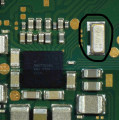
I've been doing some more work on both of these boards this weekend and I've managed to get some life out of Board 1, although I'm at a bit of a loss as to what's going on. I had been testing around the PMIC to see I could find any differences between a known working board and the faulty boards. I took a scope to what looked like a crystal/oscillator next to the chip and noticed that there was no oscillation. I checked a known good board and was able to confirm there was an oscillation. So I applied some heat and removed the crystal. I plug the board back into my PC (with crystal removed) and bing-bong! The previously dead board mounts in RCM mode (I've still got the NAND removed, so this is expected). I'm not quite sure if the crystal was causing the problem, or the application of heat fixed a broken connection under the PMIC....

With the crystal removed, I can now see the board when plugged into the load tester show 0.42A, then drops to 0A and then back up to 1.4A fast-charging....

Does anyone know what the crystal does and why the heck my Switch board has started working with it removed?
 

Attachments

  • Annotation 2020-02-16 200144 - 2.png
    Annotation 2020-02-16 200144 - 2.png
    844.7 KB · Views: 703
Last edited by SheriffBuck,

SheriffBuck

Well-Known Member
OP
Newcomer
Joined
Jan 6, 2020
Messages
98
Trophies
0
Location
Hampton, London
XP
421
Country
United Kingdom
So returning the crystal to Board 1 prevents the unit from booting, so I'm looking at getting a replacement in. I can only presume that it drives the microprocessor in the MAX77620 PMIC as both lines dive under the BGA. This board has a faulty LCD connector, so once I get that replaced, I'll report back as to what the unit is actually showing. Can anyone confirm if removing this crystal on their boards affects operation?

I worked on Board 2 last night. Re-ran my checks around the power subsystem and then focused on the testpads around the PMIC. Beside the crystal is Pin 10, Cluster E marked Reset. On this board it was low and on normal boards this is logic high. This tells me that something on the power chain is holding reset low, preventing the CPU from starting up. So I soldered a test line onto pin 10 and was about to try and buzz through and identify where the line went (aside from the CPU) when my PC which was powering the board went bing-bong and the damn thing fired up into RCM mode. Now either I've got two boards with issues around the PMIC or I've got a magic soldering iron.

I reassembled board 2 into a case and fired it up. The unit is patched unfortunately, but I was greeted with a blue screen. Now in my eyes weeks of no LCD life culminating in a blue screen is better than nothing! I know this might be terminal, but I've got a few more checks to make around the NAND connector to determine next steps. Any suggestions on a patched Switch with blue screen boot issues?????
 

SheriffBuck

Well-Known Member
OP
Newcomer
Joined
Jan 6, 2020
Messages
98
Trophies
0
Location
Hampton, London
XP
421
Country
United Kingdom
So the crystal is an NDK, although I can't find the specific part number, it appears to be similar to this one: https://www.ndk.com/en/products/search/crystal/1190959_1494.html

So I've had a response back from NDK UK to confirm that it's a STD-MUA-9 Tuning Fork Crystal running at 32.768kHz. Hopefully that will be of use to someone. https://www.ndk.com/images/products/catalog/c_NX3215SA-STD-MUA-14_e.pdf

I also now understand that the board should run without the crystal installed. It's role is to act as a timing reference against an embedded oscillator within the PMIC.
 
Last edited by SheriffBuck,

Balallax

Well-Known Member
Newcomer
Joined
Jul 27, 2017
Messages
45
Trophies
0
XP
167
Country
Brazil
Crystals normally have the function of sincronizing two sections of the board to the same frequency (like two ICs that creates pulses in diferent fequencies are clocked at the same frequency of the crystal in its output line) A damaged Crystal will surelly cause some problems with components in the way they communicate. Like both going all over the place never "talking" to each other (a REALLY bad explanation but I think it gets to the point.)
When you remove it from the board you basically "open" the circuitry and they can run independent, but surelly it will not work as expected.

Also, Swich Charges have 7.5 watts (5 volts @ 1.5 amps) and 39 watts (15 volts @ 2.6 amps). I tested it with a common phone charger and it got stuck to 0,42A draw, I dont know that samsung charger exactly are you using, but normally those quick chargers are a bit tricky to work with it. If the specifications meets the one I mentioned just ignore this part of the comment.

PS.: Sorry, I didnt read the last comment lol
 
  • Like
Reactions: SheriffBuck

SheriffBuck

Well-Known Member
OP
Newcomer
Joined
Jan 6, 2020
Messages
98
Trophies
0
Location
Hampton, London
XP
421
Country
United Kingdom
So update from tonight.

Switch 1: noticed that the PI3USB was not getting an orientation signal for USB insertion which was odd. When docked i was getting a rapidly blinking green light which suggested a negotiation panic. Suspected M92 had an issue with the CC lines. Switched out M92 and device now powers up in the dock for the first time! The TV does seem to lose connection every 5 seconds which I need to investigate, but a big breakthrough. The device does not drive internal LCD or one from another donor, so suspect FPC connector or backlight drive issue.

Switch 2: still getting the BSOD immediately on boot. Drives LCD only. This device had signs of water damage. It's patched so can't pull down keys, however was able to backup EMMC using another donor board. Plan on this one is to source a SX Core kit and try and drive payload that way. Another option might be to try an ultrasonic bath to clean under the memory and CPU....

Thoughts welcome!

Sent from my SM-G975F using Tapatalk
 
Last edited by SheriffBuck,

Ttm3

Well-Known Member
Member
Joined
May 16, 2020
Messages
248
Trophies
0
Age
43
XP
716
Country
United States
On corrosion boards I've cured ailments with flux, hot air, ultrasonic cleaner, and alcohol bath. In that order. I love this thread. Seems like anytime there is a board with .42ish amps and nothing on screen it's considered unfixable. Glad to see someone going deeper.
 
  • Like
Reactions: SheriffBuck

Theorem

Well-Known Member
Newcomer
Joined
Dec 19, 2018
Messages
57
Trophies
0
XP
1,200
Country
Czech Republic
I have one with the same symptoms too. Every voltage checks (MT, BQ) it even charges (0,45A).Recently found broken pins in LCD connector which i am about to replace. I also managed to load payload (but nothing on screen) so maybe this problem is related to LCD area shorts.Also i now completely desoldered PI3USB (it should work in handheld mode without it) and USB-C connector to be sure.
If payload sometimes works i take that Tegra chip is fine and this should be fixable.
 
Last edited by Theorem,
  • Like
Reactions: SheriffBuck

SheriffBuck

Well-Known Member
OP
Newcomer
Joined
Jan 6, 2020
Messages
98
Trophies
0
Location
Hampton, London
XP
421
Country
United Kingdom
On corrosion boards I've cured ailments with flux, hot air, ultrasonic cleaner, and alcohol bath. In that order. I love this thread. Seems like anytime there is a board with .42ish amps and nothing on screen it's considered unfixable. Glad to see someone going deeper.

Thanks for this - by sharing, hoping we can help more people! Any recommendations where I can learn more about the stages you describe? Were you applying hot air to the RAM and CPU combo under the can? I don't have an ultrasonic cleaner, but feel it's time to invest in one. Do you have any advice on choosing the right one? Thanks!
 

Ttm3

Well-Known Member
Member
Joined
May 16, 2020
Messages
248
Trophies
0
Age
43
XP
716
Country
United States
Thanks for this - by sharing, hoping we can help more people! Any recommendations where I can learn more about the stages you describe? Were you applying hot air to the RAM and CPU combo under the can? I don't have an ultrasonic cleaner, but feel it's time to invest in one. Do you have any advice on choosing the right one? Thanks!

I'm just a hobbyist trying to figure this stuff out myself. As far as flux and heat. Anywhere I see corrosion I'll drop flux and enough heat to reflow that solder & maybe add a little fresh low melt solder

I picked up a cheap ultrasonic w/heater from eBay and I use Branson ec& distilled water in it. Seems like the best ultrasonic cleaners are crest and Branson but I don't have that kind of money for this hobby.
 

SheriffBuck

Well-Known Member
OP
Newcomer
Joined
Jan 6, 2020
Messages
98
Trophies
0
Location
Hampton, London
XP
421
Country
United Kingdom
So update from tonight.

Switch 1: noticed that the PI3USB was not getting an orientation signal for USB insertion which was odd. When docked i was getting a rapidly blinking green light which suggested a negotiation panic. Suspected M92 had an issue with the CC lines. Switched out M92 and device now powers up in the dock for the first time! The TV does seem to lose connection every 5 seconds which I need to investigate, but a big breakthrough. The device does not drive internal LCD or one from another donor, so suspect FPC connector or backlight drive issue.

Switch 2: still getting the BSOD immediately on boot. Drives LCD only. This device had signs of water damage. It's patched so can't pull down keys, however was able to backup EMMC using another donor board. Plan on this one is to source a SX Pro kit and try and drive payload that way. Another option might be to try an ultrasonic bath to clean under the memory and CPU....

Thoughts welcome!

Sent from my SM-G975F using Tapatalk
So I've confirmed that Switch 1 has a backlight controller issue. I was able to use a second board to drive the backlight and confirmed that the LCD is fine! So does anyone understand where the controller IC is and whether it's possible to source a replacement?

Sent from my SM-G975F using Tapatalk
 

Ttm3

Well-Known Member
Member
Joined
May 16, 2020
Messages
248
Trophies
0
Age
43
XP
716
Country
United States
So I've confirmed that Switch 1 has a backlight controller issue. I was able to use a second board to drive the backlight and confirmed that the LCD is fine! So does anyone understand where the controller IC is and whether it's possible to source a replacement?

Sent from my SM-G975F using Tapatalk

I am also interested in this. I've got one that the backlight keeps flickering on and off
 
  • Like
Reactions: SheriffBuck

SheriffBuck

Well-Known Member
OP
Newcomer
Joined
Jan 6, 2020
Messages
98
Trophies
0
Location
Hampton, London
XP
421
Country
United Kingdom
OK. I've identified the section of the board that holds the backlight controller. I have a hunch that it's a TI TPS61163A as the pins match the datasheet and we know Nintendo source a lot of the board from TI.

The enable pin and the PWM feeds are all working, however the output stage is only giving 4v when I should be expecting something like 17v. The output stage can be measured on the left side of the large cap in the bottom left of the picture.

Looks like we have the culprit. Will order a replacement and see how we go. Picture included of the underside of the board where the controller is located.

WIN_20200530_14_40_37_Pro.jpg
 

Theorem

Well-Known Member
Newcomer
Joined
Dec 19, 2018
Messages
57
Trophies
0
XP
1,200
Country
Czech Republic
I did the same measurement on my 0,47V black screen weirdo.......i also have 4,1 V on this backlight circuit. It is board only measurement so no display is connected.


WIN_20200530_14_40_37_Pro_2.jpg
 

SheriffBuck

Well-Known Member
OP
Newcomer
Joined
Jan 6, 2020
Messages
98
Trophies
0
Location
Hampton, London
XP
421
Country
United Kingdom
I did the same measurement on my 0,47V black screen weirdo.......i also have 4,1 V on this backlight circuit. It is board only measurement so no display is connected.


View attachment 211293
Sorry. I wasn't clear. I had the backlight connected when I took the voltage measurements.

Sent from my SM-G975F using Tapatalk
 

SheriffBuck

Well-Known Member
OP
Newcomer
Joined
Jan 6, 2020
Messages
98
Trophies
0
Location
Hampton, London
XP
421
Country
United Kingdom
OK. Moved the backlight driver IC across from a donor board and we're in business. Backlight working! I have ordered TPS61163A and will retrofit that to confirm that the part is a direct match for the one fitted to the Switch.
 
  • Like
Reactions: mvmiranda

Site & Scene News

Popular threads in this forum

General chit-chat
Help Users
    Psionic Roshambo @ Psionic Roshambo: https://www.youtube.com/watch?v=A0FyqCEfD0E