


Hi all,
I modded a Switch Lite yesterday with a Picofly chip. I've succesfully modded a V1 switch with a Picofly before with ease so I thought I could do this.
Long story short, the install actually went well. I didn't struggle much and my solder joints look mostly good. Not professional, but good. Here are some screenshots.
SP1:

SP2 (less good but okay I think):

3v3. A bit too much solder on the anchor but its fine:

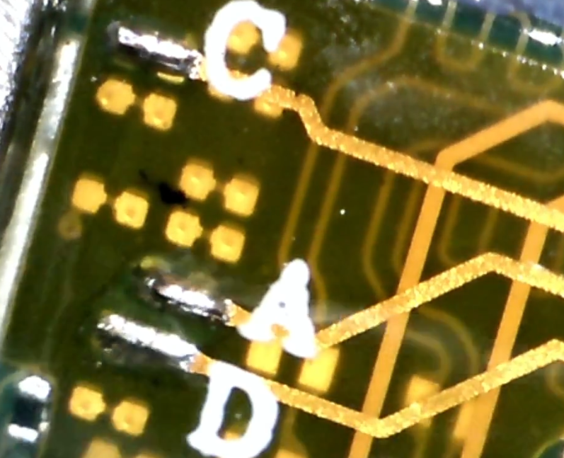
C/D/A:
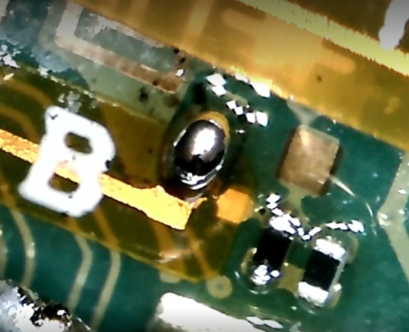
B (Again, a bit too much solder, but that shouldn't cause problems):
For the record, I never left my iron at these points for too long (especially the SP caps) to avoid burning anything out. My iron was at 310 and I used 60/40 solder with Chip Quik SMD flux.
The install works and the Picofly succesfully glitches the Switch. But the Lite never stays running for long. After a while, seemingly at random, it freezes. It sometimes freezes silently. Other times, in a more noisy way—the speaker buzzes and the screen is pixelated and green.
The only thing that, I think, I did wrong during the install is I accidentally left blobs of solder on two resistors. I cleaned up the mess but it is possible their values have been thrown off and this is what causes the freezing. One of those resistors is visible in the B picture. It's value is 8.21k.
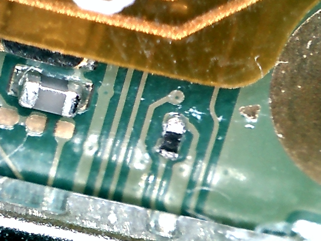
The other one is this one. it's value is 100 ohms:
If anyone knows what the value of these resistors are (or has some kind of board they can probe to test), that would be massively appreciated.
It's possible that the Switch was also this way to begin with. It was sitting in a drawer for months and I never properly tested it before I did the modchip. But I somehow doubt that's the case.
Any help would be appreciated to save this little Switch. Thank you
I modded a Switch Lite yesterday with a Picofly chip. I've succesfully modded a V1 switch with a Picofly before with ease so I thought I could do this.
Long story short, the install actually went well. I didn't struggle much and my solder joints look mostly good. Not professional, but good. Here are some screenshots.
SP1:
SP2 (less good but okay I think):
3v3. A bit too much solder on the anchor but its fine:
C/D/A:
B (Again, a bit too much solder, but that shouldn't cause problems):
For the record, I never left my iron at these points for too long (especially the SP caps) to avoid burning anything out. My iron was at 310 and I used 60/40 solder with Chip Quik SMD flux.
The install works and the Picofly succesfully glitches the Switch. But the Lite never stays running for long. After a while, seemingly at random, it freezes. It sometimes freezes silently. Other times, in a more noisy way—the speaker buzzes and the screen is pixelated and green.
The only thing that, I think, I did wrong during the install is I accidentally left blobs of solder on two resistors. I cleaned up the mess but it is possible their values have been thrown off and this is what causes the freezing. One of those resistors is visible in the B picture. It's value is 8.21k.
The other one is this one. it's value is 100 ohms:
If anyone knows what the value of these resistors are (or has some kind of board they can probe to test), that would be massively appreciated.
It's possible that the Switch was also this way to begin with. It was sitting in a drawer for months and I never properly tested it before I did the modchip. But I somehow doubt that's the case.
Any help would be appreciated to save this little Switch. Thank you


