Switch Lite won't turn on after Failed Picofly install

Shomy

Active Member
OP
Newcomer
Joined
Jul 10, 2020
Messages
29
Trophies
0
XP
95
Country
Italy
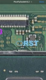
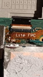
Hello, I tried installing a picofly modchip for the first time and at first everything went smooth, I managed to make it show the picofly logo, but then for some reason the console turned off and when I tried to reboot it, the modchip started flashing various errors (*=, *=*, =*).

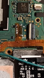
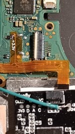
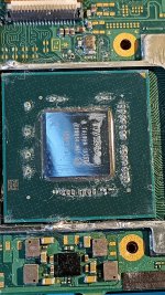
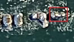
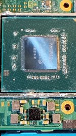
I tried resoldering everything, and ended up ripping off the left B point pad, and a CPU capacitor (SP1).

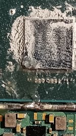
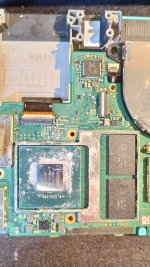
During the resoldering phase I tried many stuff, and at first I managed to boot to OFW, but then the CPU started making an high pitch noise (probably for high temperature) so I unplugged the battery many times.

Does anybody have some advice to try to fix it?
 

urherenow

Well-Known Member
Member
Joined
Mar 8, 2009
Messages
4,808
Trophies
2
Age
48
Location
Japan
XP
3,710
Country
United States
You need to post hi-res pictures for anybody to be able to even think about helping you. We don't know exactly what you did, to include what you used for resistors and mosfets. For all we know, you put the capacitor back on backwards. The B point (at least on an OLED... haven't looked a a lite board) is one of the easiest points to deal with.

EDIT: You actually have 2 pads to choose from... you didn't rip off both, right? Don't EVER tug on a wire. You touch it with the iron until you move it with the iron... and move it off before you grab it. I learned the hard way myself. And again with reballing (practicing on a board I already messed up). I grabbed a hold of an emmc with a pair of tweezers and lifted... instead of nudging out of place first... ripped like 11 pads off of the board.
 

Attachments

  • PicoflyPointB.jpg
    PicoflyPointB.jpg
    61.8 KB · Views: 5
Last edited by urherenow,

Shomy

Active Member
OP
Newcomer
Joined
Jul 10, 2020
Messages
29
Trophies
0
XP
95
Country
Italy
Here are the pictures.

The wire is connected to the pad at the right of the broken rst, I though that was rst too after I saw a schematic of the switch lite, I'm not sure though at this point.

Edit: Forgot to mention, my modchip, as you can see in the pictures, shipped with an fpc kit.
Post automatically merged:

You need to post hi-res pictures for anybody to be able to even think about helping you. We don't know exactly what you did, to include what you used for resistors and mosfets. For all we know, you put the capacitor back on backwards. The B point (at least on an OLED... haven't looked a a lite board) is one of the easiest points to deal with.

EDIT: You actually have 2 pads to choose from... you didn't rip off both, right? Don't EVER tug on a wire. You touch it with the iron until you move it with the iron... and move it off before you grab it. I learned the hard way myself. And again with reballing (practicing on a board I already messed up). I grabbed a hold of an emmc with a pair of tweezers and lifted... instead of nudging out of place first... ripped like 11 pads off of the board.
Fortunately I ripped off only the left one, I still have the right one.
 

Attachments

  • IMG_20240430_101540_SR.jpg
    IMG_20240430_101540_SR.jpg
    1.3 MB · Views: 5
  • IMG_20240430_101544_SR.jpg
    IMG_20240430_101544_SR.jpg
    1.1 MB · Views: 4
  • IMG_20240430_101411_SR.jpg
    IMG_20240430_101411_SR.jpg
    1.2 MB · Views: 5
  • IMG_20240430_101518_SR.jpg
    IMG_20240430_101518_SR.jpg
    1 MB · Views: 5
Last edited by Shomy,

Phantomas77

Well-Known Member
Member
Joined
Dec 19, 2022
Messages
284
Trophies
0
XP
724
Country
Italy
Oh boy...
Don't use those flex cable, better go with 36AWG wires.

Unsolder everything, clean everything with IPA (including CPU) and see if the console boots to OFW. Send some pics after everything is removed and cleaned.

And what in the hell is this?

1714467387631.png
 

Shomy

Active Member
OP
Newcomer
Joined
Jul 10, 2020
Messages
29
Trophies
0
XP
95
Country
Italy
Oh boy...
Don't use those flex cable, better go with 36AWG wires.

Unsolder everything, clean everything with IPA (including CPU) and see if the console boots to OFW. Send some pics after everything is removed and cleaned.

And what in the hell is this?

View attachment 434662
Unsoldered everything and still nothing.
Even plugging the charger in does nothing.

As for that cable, it was a desperate attempt to see if i could connect the B point somehow.
Post automatically merged:

Oh boy...
Don't use those flex cable, better go with 36AWG wires.

Unsolder everything, clean everything with IPA (including CPU) and see if the console boots to OFW. Send some pics after everything is removed and cleaned.

And what in the hell is this?

View attachment 434662
Here's a Pic of the cleaned board. Tried to clean the CPU too, but there was too much thermal paste so I tried to clean at least the row of caps where the flex cable was.
 

Attachments

  • IMG_20240430_113434_HDR.jpg
    IMG_20240430_113434_HDR.jpg
    1.6 MB · Views: 5
Last edited by Shomy,

urherenow

Well-Known Member
Member
Joined
Mar 8, 2009
Messages
4,808
Trophies
2
Age
48
Location
Japan
XP
3,710
Country
United States
Here's a Pic of the cleaned board. Tried to clean the CPU too, but there was too much thermal paste
Just, no. There is no such thing as "too much thermal paste" to clean. You should clean every bit off to begin with. And you should apply a proper amount of new paste when reassembling. 99% IPA and a q-tip will easily clean most of it off. The rest, you can loosen with a soft bristle toothbrush (don't apply pressure... the IPA will do all the work, and you're just moving it around) then put a tissue on top of the board and lightly brush on top of the tissue.

Also, that wire you're trying to use for the B connection is both too big, and junk. You need a single-core wire, especially at your skill level. enameled magnet wire at .3mm would be the LARGEST I would recommend for that point. Or AWG36.
 
Last edited by urherenow,

Shomy

Active Member
OP
Newcomer
Joined
Jul 10, 2020
Messages
29
Trophies
0
XP
95
Country
Italy
Just, no. There is no such thing as "too much thermal paste" to clean. You should clean every bit off to begin with. And you should apply a proper amount of new paste when reassembling. 99% IPA and a q-tip will easily clean most of it off. The rest, you can loosen with a soft bristle toothbrush (don't apply pressure... the IPA will do all the work, and you're just moving it around) then put a tissue on top of the board and lightly brush on top of the tissue.

Also, that wire you're trying to use for the B connection is both too big, and junk. You need a single-core wire, especially at your skill level. enameled magnet wire at .3mm would be the LARGEST I would recommend for that point. Or AWG36.
Managed to clean as much thermal paste as I could.

I also measured the Voltage of the Battery (~4V). The battery seems to charge as it was at ~3.8 before (though the battery itself says 3.8V) and on the cpu caps and the rest of the board there are 4V.
 

Attachments

  • IMG_20240430_122902_SR.jpg
    IMG_20240430_122902_SR.jpg
    1.4 MB · Views: 3

urherenow

Well-Known Member
Member
Joined
Mar 8, 2009
Messages
4,808
Trophies
2
Age
48
Location
Japan
XP
3,710
Country
United States
What am I looking at here? Is the CAP still there? Is it damaged? Is it bridged?
 

Attachments

  • SwitchLiteAPU_CAP.jpg
    SwitchLiteAPU_CAP.jpg
    36.4 KB · Views: 4

Shomy

Active Member
OP
Newcomer
Joined
Jul 10, 2020
Messages
29
Trophies
0
XP
95
Country
Italy
What am I looking at here? Is the CAP still there? Is it damaged? Is it bridged?
The cap is still there, though it was bridged, didn't notice it. I removed the bridge.

Edit: still no power, battery charges (4.2V now) and I measure 15V from the charger cable when unplugging the battery.
 

Attachments

  • IMG_20240430_125612_SR.jpg
    IMG_20240430_125612_SR.jpg
    1.3 MB · Views: 5
Last edited by Shomy,

Phantomas77

Well-Known Member
Member
Joined
Dec 19, 2022
Messages
284
Trophies
0
XP
724
Country
Italy
The cap is still there, though it was bridged, didn't notice it. I removed the bridge.
Does it turn on now?

That cap that you bridged supposed to be a filtering one, though I'm not sure if that short circuit could have damaged something.

In the meantime:
  • verify if you don't have short to ground on +3.3V rail and if it delivers that voltage when you try to power on the console;
  • check caps around M92T36 and BQ chips for shorts, and measure each pin of these chips in diode mode (there're plenty info online with the values that it should read).
 

psycho-neon

Well-Known Member
Member
Joined
Nov 12, 2023
Messages
136
Trophies
0
XP
335
Country
Philippines
Holycow, 😩

The ripped pad on the rst point, not sure if there is any via on that pad, have to verify. If there is, then you have to connect it.

The 3V3 line check if it is bridged. Looks like it is on the photo. Test all your power line and see if nothing is shorted.
 

Shomy

Active Member
OP
Newcomer
Joined
Jul 10, 2020
Messages
29
Trophies
0
XP
95
Country
Italy
Does it turn on now?

That cap that you bridged supposed to be a filtering one, though I'm not sure if that short circuit could have damaged something.

In the meantime:
  • verify if you don't have short to ground on +3.3V rail and if it delivers that voltage when you try to power on the console;
  • check caps around M92T36 and BQ chips for shorts, and measure each pin of these chips in diode mode (there're plenty info online with the values that it should read).
I see no shorts neither in the chips nor in the capacitor nearby.

To check for shorts I used the 3.3V point that the modchip uses and there's no short.
I'm not sure how to check if the powers delivers, i tried measuring the value between ground and that same point; 0V
 

psycho-neon

Well-Known Member
Member
Joined
Nov 12, 2023
Messages
136
Trophies
0
XP
335
Country
Philippines
I see no shorts neither in the chips nor in the capacitor nearby.

To check for shorts I used the 3.3V point that the modchip uses and there's no short.
I'm not sure how to check if the powers delivers, i tried measuring the value between ground and that same point; 0V
If i understand it correctly, you measured from ground to 1 of the 3v3 point/power point and measures 0? If so means it is shorted.
 

Shomy

Active Member
OP
Newcomer
Joined
Jul 10, 2020
Messages
29
Trophies
0
XP
95
Country
Italy
Does it turn on now?

That cap that you bridged supposed to be a filtering one, though I'm not sure if that short circuit could have damaged something.

In the meantime:
  • verify if you don't have short to ground on +3.3V rail and if it delivers that voltage when you try to power on the console;
  • check caps around M92T36 and BQ chips for shorts, and measure each pin of these chips in diode mode (there're plenty info online with the values that it should read).

If i understand it correctly, you measured from ground to 1 of the 3v3 point/power point and measures 0? If so means it is shorted.
In voltage mode it is 0, in diode mode around ~0,8
Post automatically merged:

Does it turn on now?

That cap that you bridged supposed to be a filtering one, though I'm not sure if that short circuit could have damaged something.

In the meantime:
  • verify if you don't have short to ground on +3.3V rail and if it delivers that voltage when you try to power on the console;
  • check caps around M92T36 and BQ chips for shorts, and measure each pin of these chips in diode mode (there're plenty info online with the values that it should read).
Tried again. The console still does not turn on.
The chips as I said seem to be fine, the capacitors too.

Could it be the eMMC?
As I said in the first post, I unplugged the battery many times, so I wonder if something happened to the eMMC while glitching the boot process.

I dunno tho, considering the fact that if it was the eMMC at least the modchip would have boot up.
Post automatically merged:

I think I might have found an issue.

The ribbon cable that connects the main board to the daughter board seem to have a small indent, and so I can't access the power button.
Looking online, that board should be responsible for the backlight too?

Is there a way to power on the switch without the daughter board? So at least I could be able to see if the switch itself powers on (e.g. if the cpu starts heating up.)
 
Last edited by Shomy,

psycho-neon

Well-Known Member
Member
Joined
Nov 12, 2023
Messages
136
Trophies
0
XP
335
Country
Philippines
Put the charger to power on without pressing power button. Also if you have Ammeter, measure the voltage and current draw when plugged to see if its booting.

The backlit display is from the 2nd fpc cable (right side bottom fcp, facing board towards you)
 

Shomy

Active Member
OP
Newcomer
Joined
Jul 10, 2020
Messages
29
Trophies
0
XP
95
Country
Italy
Put the charger to power on without pressing power button. Also if you have Ammeter, measure the voltage and current draw when plugged to see if its booting.

The backlit display is from the 2nd fpc cable (right side bottom fcp, facing board towards you)
Already tried it, but it does not work. I also tried shorting the test point for booting it without the daughter board.
And unfortunately i do not have amp meter for USB-C.
I guess I'll have to bring it to a repair shop. Thanks anyway.
 

Shomy

Active Member
OP
Newcomer
Joined
Jul 10, 2020
Messages
29
Trophies
0
XP
95
Country
Italy
Got an update from the repair shop.
It's unfixable. There's no power to the 3.3V rails and all cpu caps seem to be shorted to ground so they said it's the cpu shorted.

Edit: they tried removing all chips too and everything is shorted.
 
Last edited by Shomy,

Site & Scene News

Popular threads in this forum

General chit-chat
Help Users
    Xdqwerty @ Xdqwerty: @Psionic Roshambo, Hi child support im fbi!