Disney Infinity, Lego Dimensions, Skylanders Base Emulator - Project D.I.R.E.

Project D.I.R.E.
(UPDATE 29 NOVEMBER 2023)


We have been made aware that certain individuals are attempting to sell the community edition of this project on ETSY, a project that is explicitly offered for free. This action not only undermines the spirit of our community project but is also a move that capitalizes on the work of others in a very negative way. Furthermore, these sales include unauthorized distribution of bin files related to Lego, Skylanders, and Disney Infinity, which is a clear infringement of intellectual property rights. We strongly urge the community to maintain the integrity of the project by helping us address and curtail these unauthorized sales. It is essential to remind everyone that our project was created for free distribution, and it should remain that way. Your support in this matter is invaluable.

Special Thanks to the following individuals for their dedication and hard work. Without them this project would not be possible.

znxDomain -> firmware unlocker, tester, researcher
Lucky.peic -> firmware gui editor, tester, prototype, initial writeups, researcher
B47M4N -> firmware gui editor, tester, pcb and case creator, researcher, user guide writer
Bowman -> alt firmware, prototype tester
Mystic -> supplied test files, tester


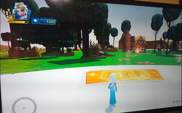
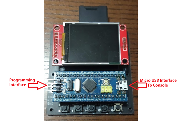
Project D.I.R.E. (Disney Infinity Reverse Engineered) is a portal emulator for Disney Infinity, Lego Dimensions, and Skylanders. This replaces the original portal in place of a custom created one to inject your own character dumps without the need for the original characters, vehicles, or playsets.

This emulator originally started several years ago after a talented coder named obiima did not release his project to the public. Obiima created and demoed a console portal emulator for 3 games: Disney Infinity, Lego Dimensions, and Skylanders. Obiima never released his project into the wild and the project he did release privately was closed firmware meaning locked to the stm32 Bluepill. This project picks up where he left off.

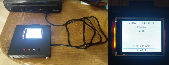
The Firmware allows this device to select between games by holding one of the buttons during boot. Specific Button usage can be found in the User Guide. You have the option of using limited onboard memory or by using an SD card you can increase the character count in your base emulator. By adding your own character files known as bin files, you can inject them into the game without having to keep your original characters.

This emulator currently works on the Wii, Wii U, PS3, and PS4.
We CAN NOT confirm if this works on the PS5 or Nintendo Switch as we do not own those consoles with these games to test with.

We have been told Skylanders plays on the Nintendo Switch but does NOT use the Portal of Power.
We have also seen footage of Disney Infinity being played on a PS5 with a PS4 base.

XBOX 360 and XBOX One are Not Yet included in this release. There is a security chip required from an Activision portal to make this work and we have not yet discovered a simple method to allow these games to work on these specific consoles.
upload_2021-8-26_20-29-42.png


upload_2021-8-27_6-51-30.png


upload_2021-8-27_6-51-46.png


Some of the files are too large to fit in this forum post and have been attached via mediafire.
All files can be found here: https://www.mediafire.com/folder/9u87thpc42j9a/Release+Package
 

Attachments

Last edited by Kfkboys,
Schematic should be included along with PCB file, are you trying to wire it on breadboard?
I recommend you use the included PCB files to order a PCB as its much easier to use that way.
I'm just trying to do this on a breadboard, given it would be easier and less cumbersome than ordering a board, that may require some soldering. I haven't soldered for a long time. Also I'm trying to find alternate components, such as a separate LCD screen and SD Card Reader. I'm trying to purchase the majority of these components locally, so I don't have to worry most of the time on postage.

Also, I checked the PCB files, and I can't seem to find any schematics. Is there something I missed amid the downloads? Or is there another means of getting the diagram? If anyone can help me with these, I will greatly appreciate it.
 
Also, I checked the PCB files, and I can't seem to find any schematics. Is there something I missed amid the downloads? Or is there another means of getting the diagram? If anyone can help me with these, I will greatly appreciate it.
Are you looking for wiring diagram for breadboard? If so, you can find it here or here.
 
So I’ve tired a new screen and re soldered everything to a new board. I’ve checked everything for shorts and there are no bridges. I still get a white screen. Does anyone had ideas?
 
How do I get rpcs3 to use the emulator. I’ve got mine working. On the log on rpcs3 it shows that the portal is there but then when I select the skylander it doesn’t go into the game
 
So I’ve tired a new screen and re soldered everything to a new board. I’ve checked everything for shorts and there are no bridges. I still get a white screen. Does anyone had ideas?

Can you post detailed pictures of the board and soldering (Im assuming you used the provided gerber files to get the PCB made) and also post detailed pictures of the screen, the STM32 board and STM32 MCU on the STM32 bluepill board so I can see the numbers on the chip.
You might have gotten clone STM32 since we did hear some clone boards not working properly.

I read your past comments here and it seems that in your case bank editor and games do recognize the board so that means the board is booting and working.

You seem to have tried new screen so that rules out defective screen.
The only causes I could think of are some issue with soldering or PCB manufacturing itself, faulty STM32, bad flash (try reflashing the firmware) or you simply got a bad STM32 clone and those were known to have issues with this firmware.
How do I get rpcs3 to use the emulator. I’ve got mine working. On the log on rpcs3 it shows that the portal is there but then when I select the skylander it doesn’t go into the game
The emulator defaults to Disney Infinity mode, hold select button (3rd button from the left) during startup to switch do skylanders mode but first try to get the screen working because you wont be able to do much without seeing the interface.
 
Can you post detailed pictures of the board and soldering (Im assuming you used the provided gerber files to get the PCB made) and also post detailed pictures of the screen, the STM32 board and STM32 MCU on the STM32 bluepill board so I can see the numbers on the chip.
You might have gotten clone STM32 since we did hear some clone boards not working properly.

I read your past comments here and it seems that in your case bank editor and games do recognize the board so that means the board is booting and working.

You seem to have tried new screen so that rules out defective screen.
The only causes I could think of are some issue with soldering or PCB manufacturing itself, faulty STM32, bad flash (try reflashing the firmware) or you simply got a bad STM32 clone and those were known to have issues with this firmware.

The emulator defaults to Disney Infinity mode, hold select button (3rd button from the left) during startup to switch do skylanders mode but first try to get the screen working because you wont be able to do much without seeing the interface.
thanks for that, ive got the emulator wokring now, just was wondering if there is a way to use it on my steam deck with skylanders or disney infinity?
 
what does "error code 1" in bank editor mean?
It's not listed anywhere in the PDF or the title post
I should mention i got it after formatting a 32gb sd card, just like the PDF tutorial said
 
I've finally managed to find some time to make my DIRE base emulator and I've run into a few issues.

I've successfully flashed the firmware to the STM32 as you can see here:
firmware.png

Here are some images of the soldering I've done (it's also my first time soldering so it probably isn't ideal):
front.jpg
back.jpg

I've checked the solder points on the front with the points on the back side as well as those traces on the back side for continuity and the multimeter beeped every single time, so there shouldn't be any short. In case I need to do some additional testing, let me know.

Sadly, I was greeted with the blank white screen when the first time I connected the emulator to the PC as you can see here:
white screen.jpg

When I opened up the Bank Editor and went into Device - Format, I've run into the "timeout" error, as you can see here:
timeout.PNG

What should I do to fix it?

This is the SD card that I'm using:
SD.jpg

I've tried flashing the 128mb.raw file to the SD card with the etcher but I've got the same result.
Post automatically merged:

I've found this post:
1. You should check all your solder joints.
2. Make sure the sd card is pushed all the way into the slot
3. Try a different USB cable
4. Reflash it using the st-link again only connecting the st-link and your bluepill
5. Double check your bluepill is 256k not 64k
1. They should be fine. At least, provided that I tested them properly (connecting front and back joints to see if there's continuity).
2. It should be. It's not the model with the click thingy, this one you just push all the way in and that's it. Here's an image:
20250320_200741.jpg
3. I've tried with two USB cables that I got with my Kindles and, unfortunately, the screen remains white and blank. Will see if i can find another one.
4. Successfully reflashed by following the guide. I've noticed that the red LED is the only one working on the STM32 board, but I've noticed that the green one worked as well for someone else in this thread. Is that normal? Here are some images:
20250320_201244.jpg


20250320_201315.jpg
5. Based on what's written during the flashing process, it should be the 64k model.

I've tried with another SD card as well, 4GB this time so I had to flash 128mb.raw to it and still nothing.
Post automatically merged:

As per Kfkboys' instructions, I've also tried flashing the firmware and connecting the SMT32 board via USB cable without anything else. Still the same "timeout" error in the Bank Editor. I'll also see about fixing my joints as they definitely aren't the best. (Thanks Kfkboys for pointing it out! ^^)
 
Last edited by Blythe93,
  • Like
Reactions: zfreeman
Just built one and works great. Honestly such a fun little project to create. Thank you to the individuals for creating this project!

On a side note, for anyone that gets "error code 1." with Bank Editor, ensure you are NOT using a SanDisk branded micro sd card. I bought a brand new SanDisk 32gb microSD card for this project and it gives me this error message constantly. Sometimes I can write 1-3 banks but most of the time I will get this error code 1 message and it will corrupt everything. I tried several other SanDisk branded SD cards I had laying around and they all have the same issue. I switched to a Samsung micro sd and it worked without any problems.

*Edit* and Yes regardless of the size SD card still flash it with the 128mb.raw file
 

Attachments

  • SanDisk.jpg
    SanDisk.jpg
    2 MB · Views: 60
  • Samsung.jpg
    Samsung.jpg
    1.9 MB · Views: 70
  • error 1.jpg
    error 1.jpg
    32.5 KB · Views: 62
  • 20250404_165707.jpg
    20250404_165707.jpg
    2.1 MB · Views: 69
what does "error code 1" in bank editor mean?
It's not listed anywhere in the PDF or the title post
I should mention i got it after formatting a 32gb sd card, just like the PDF tutorial said
Hello,
I've finally finished soldering mine, checked all the wires and i can confidently say it works...kinda?
The display doesn't light up when using the micro USB connector, only when using the debugging interface. Maybe I missed some steps/soldering points?
The SD card functionality works after a couple of tries (between 'error code 1' and 'device not found', it finally let me upload banks on external memory). I should mention that I'm using a 32gb kingston SD card. (with a generic adapter because the one it originally came with started not reading properly)

I have tried different USB cables, no change, and neither do the games recognize the device (playing on real Wii U, with the games on an external drive). Both the red and green LEDs on the board light up and flash accordingly when using either connectors
 

Attachments

  • IMG_20250418_214758.jpg
    IMG_20250418_214758.jpg
    2.8 MB · Views: 45
  • IMG_20250418_214935.jpg
    IMG_20250418_214935.jpg
    761.8 KB · Views: 44
  • IMG_20250418_215055.jpg
    IMG_20250418_215055.jpg
    4.1 MB · Views: 48
First, a big thank you to all who have contributed to this wonderful project!
I'm just here to contribute my minor innovation, which was to rotate the microcontroller and stack the display/reader above it on standard perforated board. My main motivation was to get USB to the top, but I appreciate the way that the bright LED's are hidden, the SD card is moderately protected from sideways bumps by the jumpers, and the lofted screen edges gives something to hold it by that's similar in thickness to the arcade style buttons I chose except for button 5, which I stuck at the upper right since I wanted the settings less accessible. This is for kids to use, so I built it tough by building on fiberglass then encasing it in thick layers of resin for heft and dimension, which I shaped ergonomically with sandpaper before painting with enamel. The main negative of the rotated approach is that, due to the way I mounted the buttons, I would need to use clips for accessing the pins to re-flash.

IMG_8841.jpeg

Post automatically merged:

Side view:
IMG_8822.jpeg

Post automatically merged:

For scale, here it is running atop a Wii U, next to an original pad.
IMG_8851.jpeg

Post automatically merged:

Sorry I did not take a picture of the wiring prior to applying the resin, so it's a little hard to make out what's going on, but the trace lengths are minimal for the display, at right, whereas the 4 wires for the SD reader are a bit longer going diagonally. The wires for the buttons pop up to the top for ease of routing.
IMG_8803.jpeg
IMG_8805.jpeg

Post automatically merged:

Top view, bottom view, the bottom:

IMG_8817.jpeg


IMG_8821.jpeg

IMG_8816.jpeg

Post automatically merged:

P.S. while I greatly appreciate the reference PCB design, it's few enough connections that, in my opinion, it's not necessary if you're comfortable working with wire. It's 8 wires for the LCD, 4 wires for the SD Reader, and 6-ish for the buttons (5 buttons and a common ground). I prototyped mine with a dozen molex jumper wires to test the display and memory card, soldered it up including buttons, tested, then potted in resin and painted. No significant regrets about the construction, though I think the USB port is a little feeble.
Post automatically merged:


I truly wish this were open source for academic study and personal enjoyment of video game history, regardless of Disney's copyright considerations, which is presumably why this project is kept closed. However, I'd assume that any meaningful secrets would already be within the published RPCS3 source, so why the fear of litigation?
Update: at a minimum, CEMU, RPCS3, and re_nsyshid all implement equivalent functionality to this project and are open source. Regardless, I think this project of a physical emulator is epic and I'm glad to have built it.
 
Last edited by mrMusto,
Is it possible to build the device with the screen and SD Card reader as separate components? If so, what type of screen would I need?
 
Is it possible to build the device with the screen and SD Card reader as separate components? If so, what type of screen would I need?
Yes it is, I did so... but I don't remember what display it was...
But I think it was mentioned here in the discussion...
 
IMG_8886.jpeg

Apologies for the sloppiness, but I thought I’d share the jumper (or wire if you solder) connections to be made between the microcontroller and the card reader / screen.
Post automatically merged:

Is it possible to build the device with the screen and SD Card reader as separate components? If so, what type of screen would I need?
Absolutely! Refer to the schematic I just posted though and you’ll see there are just 4 additional lines for enabling the reader when it’s integrated with the LCD, but if it’s separate, it might need ground and 3.3/5v of its own? Out of curiosity, what is your objective though? Card switcher?
Post automatically merged:

Hello,
I've finally finished soldering mine, checked all the wires and i can confidently say it works...kinda?
The display doesn't light up when using the micro USB connector, only when using the debugging interface. Maybe I missed some steps/soldering points?
The SD card functionality works after a couple of tries (between 'error code 1' and 'device not found', it finally let me upload banks on external memory). I should mention that I'm using a 32gb kingston SD card. (with a generic adapter because the one it originally came with started not reading properly)

I have tried different USB cables, no change, and neither do the games recognize the device (playing on real Wii U, with the games on an external drive). Both the red and green LEDs on the board light up and flash accordingly when using either connectors
My advice for you, Blythe93, and anyone else suck with this project is to follow below and report back:

Step 0: Buy what you need--in addition to a fresh, unsoldered BluePill (<$10) and Display/Reader ($15), you will need at least a dozen "female-to-female breadboard jumper wires" of length ~4-8 inches long like shown:
IMG_8894.jpeg

At $5-10 for a lifetime supply if you don't already have them, IMHO a pack of jumpers is a "requirement" to verify the microcontroller is happy with the display/reader BEFORE soldering.

Step 1: Use some jumper wires to program the BluePill:
IMG_8897.jpeg


Step 2: Plug into a Windows PC via USB and use the software to create a bank, upload some .bin's, etc. to make sure your microcontroller is good.

Step 3: Connect the 8 jumpers from the microcontroller (pins B3 thru 3.3v) to the display (pins VCC thru LED) as per the schematic I posted, then plug it into any powered USB source to check your display. It will look something like this:
IMG_8901.jpeg


Step 4: Attach the 4 jumpers from the microcontroller (pins B12 thru B15) to the reader pins (SD_CS thru SD_SCK or equivalent) as also shown in the schematic, then plug into a Windows PC to ensure you can use the bank software to create banks on the card and save some .bin's to them. This presumes you have a small card or have flashed the special image to pretend to be 128MB.

Step 5: Take a picture, since I didn't, and post back with your success or failure! You can't actually load characters without buttons, but you can make sure your console detects it as a base nevertheless.

Step 6: Proceed to soldering knowing that you have working components...

~~ I'm glad to help some of you through this project, but unless you follow something like the above to make sure everything is good before soldering, it's nearly impossible to tell whether you have gone wrong in your connections/soldering or whether a component is at fault. Sorry for the extra 5min and 5 dollars, but seeing how some people are getting stuck in a tough state to troubleshoot, I think jumping the parts to test before soldering should be standard/best practice. ~~
 
Last edited by mrMusto,
View attachment 508678
Apologies for the sloppiness, but I thought I’d share the jumper (or wire if you solder) connections to be made between the microcontroller and the card reader / screen.
Post automatically merged:


Absolutely! Refer to the schematic I just posted though and you’ll see there are just 4 additional lines for enabling the reader when it’s integrated with the LCD, but if it’s separate, it might need ground and 3.3/5v of its own? Out of curiosity, what is your objective though? Card switcher?
Post automatically merged:


My advice for you, Blythe93, and anyone else suck with this project is to follow below and report back:

Step 0: Buy what you need--in addition to a fresh, unsoldered BluePill (<$10) and Display/Reader ($15), you will need at least a dozen "female-to-female breadboard jumper wires" of length ~4-8 inches long like shown:
View attachment 508713
At $5-10 for a lifetime supply if you don't already have them, IMHO a pack of jumpers is a "requirement" to verify the microcontroller is happy with the display/reader BEFORE soldering.

Step 1: Use some jumper wires to program the BluePill:
View attachment 508722


Step 2: Plug into a Windows PC via USB and use the software to create a bank, upload some .bin's, etc. to make sure your microcontroller is good.

Step 3: Connect the 8 jumpers from the microcontroller (pins B3 thru 3.3v) to the display (pins VCC thru LED) as per the schematic I posted, then plug it into any powered USB source to check your display. It will look something like this:
View attachment 508723

Step 4: Attach the 4 jumpers from the microcontroller (pins B12 thru B15) to the reader pins (SD_CS thru SD_SCK or equivalent) as also shown in the schematic, then plug into a Windows PC to ensure you can use the bank software to create banks on the card and save some .bin's to them. This presumes you have a small card or have flashed the special image to pretend to be 128MB.

Step 5: Take a picture, since I didn't, and post back with your success or failure! You can't actually load characters without buttons, but you can make sure your console detects it as a base nevertheless.

Step 6: Proceed to soldering knowing that you have working components...

~~ I'm glad to help some of you through this project, but unless you follow something like the above to make sure everything is good before soldering, it's nearly impossible to tell whether you have gone wrong in your connections/soldering or whether a component is at fault. Sorry for the extra 5min and 5 dollars, but seeing how some people are getting stuck in a tough state to troubleshoot, I think jumping the parts to test before soldering should be standard/best practice. ~~

On another note, as a new member I can't message the original poster to ask for thoughts on what qualities a hypothetical reference collection of .bin's should have. I also can't ask for clarification on the ethics of distributing any modifications or the know-how to make changes to the firmware. Bummer.
Hello,
Just tried your advice, here's the final connections.
Unfortunately, the screen still doesn't light up and when connecting it, the bank editor doesn't recognize the SD card.
I don't know what to do or where it went wrong.
(due to the images being too big to be uploaded, they're here)
 
I'm having a problem where after I flash the firmware it just blinks red. I have a 64k version so that shouldn't be a problem.
 
Sorry for neglecting your message!
If neither the SD card nor the display are working when connected, then I think there may be something the matter with your microcontroller. Let's revisit step 2 to make sure you're on track there: were you able to upload a .bin to the controller, disconnect it, reconnect it, and see the .bin as saved internally from within the windows software? Relatedly, is it recognized as a game pad device when you plug it into a console? This rudimentary functionality should be afforded by just the microcontroller with nothing attached, and should be verified IMHO before bothering to connect up the SD card or screen.
This is such a great project; my only complaint with the end result is handling LARGE .bin collections (slow to browse)--it seems better tailored to a curated collection of virtual figures. [AH HAH! There is seek but my buttons weren't making continuous contact to trigger it!] My only complaint with the original instructions is that they forego verifying the components before soldering, making it super difficult to help people who get stuck.
Kindly report back on whether your blue pill is working standalone; if you have any doubts, my suggested next step would be to obtain an alternative from a different supplier and try that...
Post automatically merged:

I'm having a problem where after I flash the firmware it just blinks red. I have a 64k version so that shouldn't be a problem.
Hi,
My advice is to obtain a microcontroller from a different supplier and try that! It's just 4 wires to jumper to flash the firmware, and it should be able to have a .bin saved to it with the Windows software.
Mind sharing where you got yours?
I picked up a 3-pack from Amazon, and validated all 3 but only built out one with a screen. I think it was ~18USD for the microcontroller 3-pack OR a single display/reader. The writer was cheaper at more like ~$7USD.
 
Last edited by mrMusto,
I was able to flash the firmware and get it to work with the bank editor, put a bin file on and everything. however, the screen is blank/white and not displaying anything.
Post automatically merged:

I was able to flash the firmware and get it to work with the bank editor, put a bin file on and everything. however, the screen is blank/white and not displaying anything.
Sorry for neglecting your message!
If neither the SD card nor the display are working when connected, then I think there may be something the matter with your microcontroller. Let's revisit step 2 to make sure you're on track there: were you able to upload a .bin to the controller, disconnect it, reconnect it, and see the .bin as saved internally from within the windows software? Relatedly, is it recognized as a game pad device when you plug it into a console? This rudimentary functionality should be afforded by just the microcontroller with nothing attached, and should be verified IMHO before bothering to connect up the SD card or screen.
This is such a great project; my only complaint with the end result is handling LARGE .bin collections (slow to browse)--it seems better tailored to a curated collection of virtual figures. My only complaint with the original instructions is that they forego verifying the components before soldering, making it super difficult to help people who get stuck.
Kindly report back on whether your blue pill is working standalone; if you have any doubts, my suggested next step would be to obtain an alternative from a different supplier and try that...
Post automatically merged:


Hi,
My advice is to obtain a microcontroller from a different supplier and try that! It's just 4 wires to jumper to flash the firmware, and it should be able to have a .bin saved to it with the Windows software.
Mind sharing where you got yours?
I picked up a 3-pack from Amazon, and validated all 3 but only built out one with a screen. I think it was ~18USD for the microcontroller 3-pack OR a single display/reader. The writer was cheaper at more like ~$7USD.
This is my second account here. My microUSB connecter was bad so I used another and was able to get it to work except for the screen, I checked connections and solder joints and they seem all good.
 

Site & Scene News

Popular threads in this forum