- Joined
- Oct 29, 2013
- Messages
- 1,459
- Reaction score
- 569
- Trophies
- 1
- Location
- Brazil, Sao Paulo
- Website
- www.gamemod.com.br
- XP
- 1,759
- Country

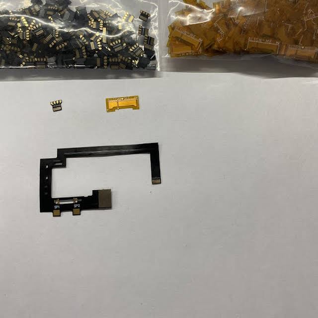
Actually you only need 5 since the GND is already being "pulled" from the long CPU flat cable.Thanks for letting us know!
Nice, but in the end we still have to solder 6 wires.
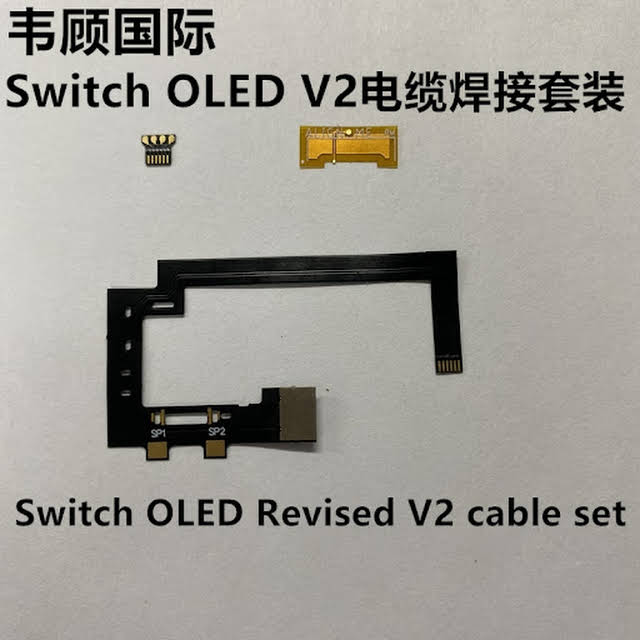
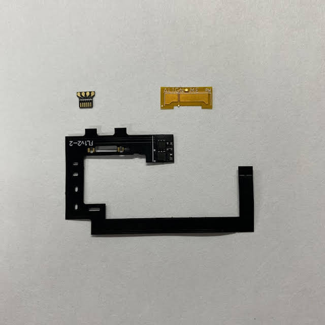
PS for newbies like me: on the core installation there’s another step: fold the ribbon cable and connect the adapter - in which the 4 wires are soldered to - to the modchip motherboard.
")
Mine was updated before I install.Question...Can the SX Core be flashed with Spacecraft before it is installed? or does it need to be in the switch and powered on before it can be flashed?
I used an original SX Lite updated with Spacecraft-NX 0.2.0.