Picofly in V2 shows “no sd card” but fails to boot Hekate/OFW

cunca

Member
OP
Newcomer
Joined
Jan 28, 2024
Messages
6
Trophies
0
Age
22
XP
24
Country
United States
Hello,

I installed a Picofly a few days ago in my Switch. After a few hours of work I finally booted it up and got the “no sd card” screen as expected.

Unfortunately, I quickly discovered some serious issues. Attempting to boot Hekate just gives a black screen, and holding vol +/- to boot from OFW gives a blue screen.

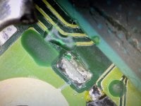
The chip itself glitches perfectly on first attempt, I’ve reinstalled it and very carefully checked all solder points to no avail. Removing the chip fully again leaves me with a blue screen on boot.

Now — after searching for a solution, I tried booting a UMS payload, and to my surprise it worked; supposedly because it runs solely off the APU’s iRAM instead of the dedicated RAM, but I have no reason to think my RAM is the issue. I didn’t touch it.

Advice would be greatly appreciated.
 

Hassal

Well-Known Member
Member
Joined
Apr 22, 2023
Messages
561
Trophies
0
Age
24
XP
510
Country
United Arab Emirates
Dead CPU
Dead eMMC
Dead RAM

Or, like some people in the forum that scrapped traces on PCB. I'd just inspect for any damage before attempting anything else.
 

cunca

Member
OP
Newcomer
Joined
Jan 28, 2024
Messages
6
Trophies
0
Age
22
XP
24
Country
United States
Dead CPU
Dead eMMC
Dead RAM

Or, like some people in the forum that scrapped traces on PCB. I'd just inspect for any damage before attempting anything else.

I believe I addressed these: the UMS server runs successfully, indicating the CPU is alright, and the system fails to boot Hekate which says to me that the eMMC is not at fault.

Dead RAM seems like the remaining possibility, but I came nowhere near it and have been unable to find any damage.

If there is a diagram that can assist with locating the relevant traces for RAM, that would be extremely helpful.
 

Hassal

Well-Known Member
Member
Joined
Apr 22, 2023
Messages
561
Trophies
0
Age
24
XP
510
Country
United Arab Emirates
I believe I addressed these: the UMS server runs successfully, indicating the CPU is alright, and the system fails to boot Hekate which says to me that the eMMC is not at fault.

Dead RAM seems like the remaining possibility, but I came nowhere near it and have been unable to find any damage.

If there is a diagram that can assist with locating the relevant traces for RAM, that would be extremely helpful.
Neither of that is true.
But I'll give you the benefit of the doubt you may have damaged traces connecting the RAM.
No diagram is required for this as all traces are sitting between SoC and RAM are visible under the shield.
 

cunca

Member
OP
Newcomer
Joined
Jan 28, 2024
Messages
6
Trophies
0
Age
22
XP
24
Country
United States
Neither of that is true.
But I'll give you the benefit of the doubt you may have damaged traces connecting the RAM.
No diagram is required for this as all traces are sitting between SoC and RAM are visible under the shield.

I don't see how the system would be able to successfully glitch and run a payload if the APU was damaged. Same thing for the eMMC; if it was completely fried I'd likely be unable to glitch at all, and if it was just scrambled I'd still be able to boot Hekate.

The RAM looks pristine, there are no scratched or exposed traces, and as I stated before, I didn't come close to the RAM during my installation.

I don't expect a miracle, but a way to identify which component is damaged would give me peace of mind. As of right now I've resorted to blaming it on static discharge or invisible solder flecks.
 

deeps

Well-Known Member
Member
Joined
Jul 3, 2007
Messages
447
Trophies
1
XP
1,237
Country
blue screen on ofw boot means damaged or broken ram, or traces to ram, or apu interface against ram. Fixing a blue screen is very rare. Your switch is most likely permanently dead.
 

Frkn

Member
Newcomer
Joined
Dec 20, 2023
Messages
6
Trophies
0
Age
38
XP
38
Country
Canada
Hi, I have the exact same issue on my 1-month old OLED. Installation went fine, with all readings within specs. Picofly (rp2040 from aliexpress) glitches properly, and then black screen. Blue screen if I try to boot to OFW. Tried both 2.75 and 2.73 firmwares.

From what I've found, I'm leaning towards the fact that for whatever reason, boot0/1 gets corrupted on the emmc when the picofly injects its payload the first time it boots. I've ordered an emmc to USB adapter, which I'll receive in a couple weeks and will be able to verify that then. I also ordered Instinct-NX v6s chips in order to try these instead of the Picofly.

Where did you get the UMS playload from ? I'll test it to see if I get the same results that you do, as I was about to reflow the APU, thinking that I maybe had applied too much heat when soldering the ribbon cable to the APU and broke / bridged some balls.
Post automatically merged:

@jihoko, Why the laugh? Am I completely off-track thinking it might be a emmc issue due to a bad picofly chip?
 
Last edited by Frkn,
  • Haha
Reactions: jkyoho

cunca

Member
OP
Newcomer
Joined
Jan 28, 2024
Messages
6
Trophies
0
Age
22
XP
24
Country
United States
blue screen on ofw boot means damaged or broken ram, or traces to ram, or apu interface against ram. Fixing a blue screen is very rare. Your switch is most likely permanently dead.
Thank you for a very empty contribution --- all of this was present in the thread already. I understand that it's likely permanently dead, but in the off chance that I decide to try again in the future, I'd like to know where I went wrong. I soldered cleanly and there is no visible damage.

Hi, I have the exact same issue on my 1-month old OLED. Installation went fine, with all readings within specs. Picofly (rp2040 from aliexpress) glitches properly, and then black screen. Blue screen if I try to boot to OFW. Tried both 2.75 and 2.73 firmwares.

From what I've found, I'm leaning towards the fact that for whatever reason, boot0/1 gets corrupted on the emmc when the picofly injects its payload the first time it boots. I've ordered an emmc to USB adapter, which I'll receive in a couple weeks and will be able to verify that then. I also ordered Instinct-NX v6s chips in order to try these instead of the Picofly.

Where did you get the UMS playload from ? I'll test it to see if I get the same results that you do, as I was about to reflow the APU, thinking that I maybe had applied too much heat when soldering the ribbon cable to the APU and broke / bridged some balls.
Post automatically merged:

@jihoko, Why the laugh? Am I completely off-track thinking it might be a emmc issue due to a bad picofly chip?

That's interesting. Any idea what format the boot0/1 partitions are on the eMMC? When trying to mount those on my PC using the UMS server it failed to mount those two partitions, I just assumed it was due to a funky filesystem or something.

I've attached the UMS payload. The bridged balls theory is another explanation, but considering the thickness of the APU it seems to me that it would take more heat than I gave it to cause bridging. It's just weird.
Post automatically merged:

@Frkn Oh, re the bad chip: mine was a brand new RP2040-Zero from Waveshare. I don't have any reason to think that it was at fault.
 

Attachments

  • ums-loader.zip
    30.5 KB · Views: 13
Last edited by cunca,

deeps

Well-Known Member
Member
Joined
Jul 3, 2007
Messages
447
Trophies
1
XP
1,237
Country
Thank you for a very empty contribution --- all of this was present in the thread already. I understand that it's likely permanently dead, but in the off chance that I decide to try again in the future, I'd like to know where I went wrong. I soldered cleanly and there is no visible damage.


That's interesting. Any idea what format the boot0/1 partitions are on the eMMC? When trying to mount those on my PC using the UMS server it failed to mount those two partitions, I just assumed it was due to a funky filesystem or something.

I've attached the UMS payload. The bridged balls theory is another explanation, but considering the thickness of the APU it seems to me that it would take more heat than I gave it to cause bridging. It's just weird.
Post automatically merged:

@Frkn Oh, re the bad chip: mine was a brand new RP2040-Zero from Waveshare. I don't have any reason to think that it was at fault.

Picofly works by writing BCT and sdloader into boot0. When it glitches successfully and runs a payload, nothing else will be read from the emmc. If the emmc was the problem, you would not be able to run ums-loader either.
 

Frkn

Member
Newcomer
Joined
Dec 20, 2023
Messages
6
Trophies
0
Age
38
XP
38
Country
Canada
Thank you for a very empty contribution --- all of this was present in the thread already. I understand that it's likely permanently dead, but in the off chance that I decide to try again in the future, I'd like to know where I went wrong. I soldered cleanly and there is no visible damage.


That's interesting. Any idea what format the boot0/1 partitions are on the eMMC? When trying to mount those on my PC using the UMS server it failed to mount those two partitions, I just assumed it was due to a funky filesystem or something.

I've attached the UMS payload. The bridged balls theory is another explanation, but considering the thickness of the APU it seems to me that it would take more heat than I gave it to cause bridging. It's just weird.
Post automatically merged:

@Frkn Oh, re the bad chip: mine was a brand new RP2040-Zero from Waveshare. I don't have any reason to think that it was at fault.
Here's information on the format of the NAND:
switchbrew.org/wiki/Flash_Filesystem

I will have everything in hand in ~ 3 weeks to read/write from/to the eMMC and reball the APU if needed (I've bought another dead OLED that I'm trying to revive). As for the APU, I'm right there with you, I didn't put nearly enough heat soldering that ribbon cable to cause the balls to melt, and even if that was the case, the board never moved, so they would have kept their form and resolidified. Both the APU and the board absorb a lot of heat before solder can melt, and there's no way the fine tip on my iron could output that kind of heat.

I'll recheck around the APU tonight in order to see if I can find a broken trace somewhere, as that would be the most likely issue.

The only other way I can see the APU being bridged is that when cutting the shield a tiny metal shaving dropped and lodged itself underneath the APU.
Post automatically merged:

Picofly works by writing BCT and sdloader into boot0. When it glitches successfully and runs a payload, nothing else will be read from the emmc. If the emmc was the problem, you would not be able to run ums-loader either.

Thanks for the info.
Post automatically merged:

Update on my situation: Turns out I DID have a cut trace near the CLK (D) point. I scratched the board a bit when cutting the shield, cleaned and checked it and I thought I only removed a bit of mask, so I masked it out and called it a day.

So yeah, did a proper repair and blue screen is gone. I now have to reinstall the chip.
 

Attachments

  • 250FAEB3-5908-49D5-BE28-784BD0D6E20B.jpeg
    250FAEB3-5908-49D5-BE28-784BD0D6E20B.jpeg
    4.8 MB · Views: 22
Last edited by Frkn,

cunca

Member
OP
Newcomer
Joined
Jan 28, 2024
Messages
6
Trophies
0
Age
22
XP
24
Country
United States
You should check the traces and resistors near CPU shield, some people may damaged it during take off the shield but they did not aware.
I've tried quite hard to find damage but ... nothing.

It's possible that I burnt the resistors near the RST point but I'm not optimistic; I'm going to replace them anyways.
 

Frkn

Member
Newcomer
Joined
Dec 20, 2023
Messages
6
Trophies
0
Age
38
XP
38
Country
Canada
I've tried quite hard to find damage but ... nothing.

It's possible that I burnt the resistors near the RST point but I'm not optimistic; I'm going to replace them anyways.
What type of magnification are you using? Really take your time looking from different angles, as it may be under a piece of shield. The trace I repaired didn’t look broken and even tested ok for continuity, but resistance was probably very high (didn’t check for it, I just put a bit of solder and retested the console).

You’ll need a multimeter to test that resistor and have a clear answer.
 

Site & Scene News

Popular threads in this forum

General chit-chat
Help Users
  • No one is chatting at the moment.
    Psionic Roshambo @ Psionic Roshambo: https://www.youtube.com/watch?v=ZJewzRHdH8c