Hacking HWFly Lite modchip does not start

Gesztiboy

Member
OP
Newcomer
Joined
May 30, 2022
Messages
7
Trophies
0
Location
Hungary
XP
77
Country
Hungary
Hello All,

In the last month I ordered a HWFly Lite modchip via Ali and I soldered it (I used mostly sth*tix videos, he has pretty good vids) but somehow the modchip does not start blinking, doing the glitch or doing anything. The Switch Lite turns on without any problems, no BSOD, no black screen, etc...and I still don't see the imfamous "space rocket and NO SD" screen on my Switch Lite or Hekate, only the OFW boots


Just in case, I checked, what happens, if I connect the chip via debug cable to my PC and then the green LED turns on.
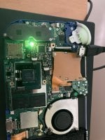
IMG_1182.JPG

If I measure the new solder points with multimeter, it's beeping, thus the ribbon cable won't be broken

Just a picture about the installation
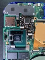
IMG_1179.JPG

Does anyone have idea/suggestion, what can cause the problem? How can I measure it, if the soldering cause the problem? Can anyone provide a valid soldering guide, which points are need to solder? What can be the effects of the broken modchip? Any idea much appreciated
 

impeeza

¡Kabito!
Member
Joined
Apr 5, 2011
Messages
6,359
Trophies
3
Age
46
Location
At my chair.
XP
18,708
Country
Colombia
Hello All,

In the last month I ordered a HWFly Lite modchip via Ali and I soldered it (I used mostly sth*tix videos, he has pretty good vids) but somehow the modchip does not start blinking, doing the glitch or doing anything. The Switch Lite turns on without any problems, no BSOD, no black screen, etc...and I still don't see the imfamous "space rocket and NO SD" screen on my Switch Lite or Hekate, only the OFW boots
View attachment 311937

Just in case, I checked, what happens, if I connect the chip via debug cable to my PC and then the green LED turns on.
View attachment 311934

If I measure the new solder points with multimeter, it's beeping, thus the ribbon cable won't be broken

Just a picture about the installation
View attachment 311933

Does anyone have idea/suggestion, what can cause the problem? How can I measure it, if the soldering cause the problem? Can anyone provide a valid soldering guide, which points are need to solder? What can be the effects of the broken modchip? Any idea much appreciated
the picture isn't clear but seems what the welds on the CPU's condensers are in short.
 
  • Like
Reactions: xoINARIox

impeeza

¡Kabito!
Member
Joined
Apr 5, 2011
Messages
6,359
Trophies
3
Age
46
Location
At my chair.
XP
18,708
Country
Colombia
on that picture doesn't appears to be on short.

The switch could work with these on short, because part of the "magic" of the core/HWFLY is to put down the CPU's voltages on specific time and frecuencies to take the CPU to a vulnerable mode and use to load unsigned firmware.
 

OrganixXx

Member
Newcomer
Joined
Jan 6, 2019
Messages
19
Trophies
0
Age
39
XP
301
Country
Germany
I have not tried but I think with shorted caps it won't turn on. The magic is to pull the voltage in the right moment deep enough to glitch the bct check. Not to short it continuesly.
 

Gesztiboy

Member
OP
Newcomer
Joined
May 30, 2022
Messages
7
Trophies
0
Location
Hungary
XP
77
Country
Hungary
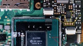
the hwfly gets no power!

Check this:
View attachment 311958
I was thinking before but I didn’t know where does the chip gets the power. I thought via the ribbon cable which is not connected to the CPU. Any idea How can I check/measure if the chip gets power or not? I checked the soldering and both sides of the bigger capacitor are covered. I’ll doublecheck later
 

Ferris1000

Well-Known Member
Member
Joined
Mar 10, 2017
Messages
248
Trophies
0
Age
33
Location
Titan
XP
2,362
Country
Germany
I would try to fix the bad looking solder joints on sp1 and sp2 by using Noa little bit of noclean flux, flux will make the solder joints look clean and show if there is a connection issue or solder bridge. Left side of sp1 doesn't look soldered which would prevent the console from booting, I already had a console where one of those were the cause
 

Gesztiboy

Member
OP
Newcomer
Joined
May 30, 2022
Messages
7
Trophies
0
Location
Hungary
XP
77
Country
Hungary
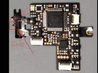
check both left and right side of sp1 ans sp2 to gnd, it should beep
Checked, all four beeps

check both 3.3v and gnd, it should beep!
Just for curiousity I checked those joints with tweezers and the left side of the soldering wasn't in contact. Let me try to resolder those
I would try to fix the bad looking solder joints on sp1 and sp2 by using Noa little bit of noclean flux, flux will make the solder joints look clean and show if there is a connection issue or solder bridge. Left side of sp1 doesn't look soldered which would prevent the console from booting, I already had a console where one of those were the cause
Even if those four joints were beep, do I need to resolder?
 

Gesztiboy

Member
OP
Newcomer
Joined
May 30, 2022
Messages
7
Trophies
0
Location
Hungary
XP
77
Country
Hungary
Gentlemen,

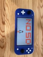
I think we're done! Now the chip gets power, the LED pulsing and at the end it turns into green!


And the rocket with NO SD comes in as well
IMG_1190.JPG

In this case the lack of power caused the problem but it's recommended to measure the CMD/CLK/DAT0/RST points and recheck with tweezers/resolder the joints one by one. So thank you for the help for Everyone!

A sidenote for those who will experience the same in the future:
- If you have no experience in soldering (as I had) don't worry, buy SMD/THT/microsoldering practice board and practice. It worth, really
- Using good quality tweezers, flux, 60/40 solder, soldering iron and I-Tip or similar is recommended. I used cheap tweezers in the beginning (during practice) and I couldn't hold the small capacitors, ribbon cables normally, it just caused headache
- I didn't use microscope, only "third hand with magnifying glass", the ribbon cable under the modchip was a bit difficult but not impossible. It took a few hours to solder it. And the same for the cable on the CPU. Only for one project, microscope would be overkill but longterm, it is recommended for microsoldering
- Be patient during soldering. Don't rush, otherwise, it can cause trouble
- Doublecheck the joints with tweezers, push down the cable and resolder if need (this was the problem in my case)

Once again, thank you for the help! Now I'm going to create a NAND backup and install CFW/EmuNAND :)
 
Last edited by Gesztiboy,
  • Like
Reactions: de9ed and impeeza

Site & Scene News

Popular threads in this forum

General chit-chat
Help Users
  • No one is chatting at the moment.
    K3Nv2 @ K3Nv2: Well start walking towards them +1