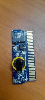
EZ-Flash Omega bricked?

geocamus

Member
Newcomer
Joined
Jul 1, 2016
Messages
16
Trophies
0
Age
54
XP
83
Country
Spain
For anyone arriving at this thread looking for answers regarding their non booting (no Nintendo logo at start) EZ-Flash Omega.

If replacing the crystal oscillator according to the "basic repair guide" (mentioned above) doesn't repair it then maybe the EEPROM (U3) chip is malfunctioning. In this case it was a bad "Puya P25D40H".

I repaired it by getting a new EEPROM, in this case a "M25P40" by "ST" I chose this one because my two Omegas had it.

It was flashed with a BIN file created with offsets from a known working Omega EEPROM dump and offsets from the bad EEPROM.
It appeard to me that each EEPROM dump became unique after offset 0x00030000.
I used a hex editor (HxD) and pasted everything from 0x0 -> 0x0002FFFF from the good Omega and then the rest from 0x00030000 and beyond from the bad Omega and saved as new 512KB .BIN file.

For the dumping and flashing:
The EEPROM was de-soldered from the Omega and soldered on to a socket adapter board connected on top of a CH341B programmer (check Amazon, eBay, Aliexpress) and was used together with NeoProgammer.

Attached to this post you can download the .BIN file with the first offsets from the good Omega at FW and Kernel 1.09.
You'll also need the ezkernel.bin v1.09 in the root of your SDcard if your Omega isn't updated to 1.09 since it will want to update if it detects and older version.

One give away that the EEPROM was failing was that different CRC codes were calculated each time NeoProgrammer read it.
The more obvious one was that the data was being changed each time it was flashed and couldn't be verified afterwards.
This wasn't an issue with the new EEPROM.

Maybe the @EZ-Flash2 team could advice us what to do in the case that the EEPROM is completley corrupt and there's nothing to salvage or maybe if possible divorce the EEPROM from the rest of the cart in their next update?

Good luck!

-edit for clarification


Hello my brother,
Maybe you can help me, I changed the U3 chip and reprogrammed it. Previously I had already made the change of the Crystal.

But when I finished changing the U3 chip and tested it, I was surprised that this happened:

1. I insert the cartridge in the GBA or GBA SP console, in both.
2. I turn on the console, and it doesn't turn on at all with the cartridge inside.
3. If I remove the cartridge, it turns on without any problem.

I have checked that I could have short and I have nothing, the U3 chip I programmed it well and even tried with another new chip the M25P40 programmed and soldered it also to test and same behavior, the consoles do not turn on with the cartridge inside.

Do you think I can check something else? I comment that before changing the U3 chip if the consoles turned on with the cartridge inside, but did not pass the Nintendo Logo.
 

moon_rabbit

Well-Known Member
Newcomer
Joined
May 6, 2022
Messages
97
Trophies
0
Age
34
Location
kor
XP
230
Country
Korea, South
Hello my brother,
Maybe you can help me, I changed the U3 chip and reprogrammed it. Previously I had already made the change of the Crystal.

But when I finished changing the U3 chip and tested it, I was surprised that this happened:

1. I insert the cartridge in the GBA or GBA SP console, in both.
2. I turn on the console, and it doesn't turn on at all with the cartridge inside.
3. If I remove the cartridge, it turns on without any problem.

I have checked that I could have short and I have nothing, the U3 chip I programmed it well and even tried with another new chip the M25P40 programmed and soldered it also to test and same behavior, the consoles do not turn on with the cartridge inside.

Do you think I can check something else? I comment that before changing the U3 chip if the consoles turned on with the cartridge inside, but did not pass the Nintendo Logo.

If it doesn't turn on with the cartridge in, it means it's shorted.
Check the area you touched.
If you don't see it anywhere, it might be under the BGA.
 
  • Like
Reactions: geocamus

geocamus

Member
Newcomer
Joined
Jul 1, 2016
Messages
16
Trophies
0
Age
54
XP
83
Country
Spain
If it doesn't turn on with the cartridge in, it means it's shorted.
Check the area you touched.
If you don't see it anywhere, it might be under the BGA.

Thank you, I will check for short points. Although I did not see anything and I only touched the chip when desoldering/soldering. What worries me is that it does not remove the clock battery from the board when working, will it have affected something that was put the chip U3 and did not remove the Battery before?

Do you know if there is any circuit diagram to check input/output voltages on the board?
 
Last edited by geocamus,

moon_rabbit

Well-Known Member
Newcomer
Joined
May 6, 2022
Messages
97
Trophies
0
Age
34
Location
kor
XP
230
Country
Korea, South
Thank you, I will check for short points. Although I did not see anything and I only touched the chip when desoldering/soldering. What worries me is that it does not remove the clock battery from the board when working, will it have affected something that was put the chip U3 and did not remove the Battery before?

Do you know if there is any circuit diagram to check input/output voltages on the board?
The battery doesn't seem to matter.
Search for gba cartridge pinout to see the basic pin configuration.
You won't find schematics specifically for the omega.
My guess is that it could be the SD card slot right next to it, or the BGA chip on the other side.
Did you work with hot air?
If you were simply soldering with a soldering iron, it's unlikely to be a problem.
 
Last edited by moon_rabbit,
  • Like
Reactions: geocamus

geocamus

Member
Newcomer
Joined
Jul 1, 2016
Messages
16
Trophies
0
Age
54
XP
83
Country
Spain
The battery doesn't seem to matter.
Search for gba cartridge pinout to see the basic pin configuration.
You won't find schematics specifically for the omega.
My guess is that it could be the SD card slot right next to it, or the BGA chip on the other side.
Did you work with hot air?
If you were simply soldering with a soldering iron, it's unlikely to be a problem.


Thank you for your answer.
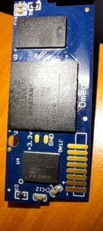
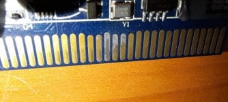
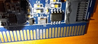
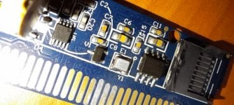
Note that I did have some small details when soldering/desoldering:

1. I stained and calcined tin to 3 tracks of the reader strip of the board, but it worked that way before, so I doubt that this is the reason for the failure.

2. Slightly the edge where the MicroSD is inserted melted, that happened this time I changed the U3 chip and that was the most recent change I noticed after desoldering/soldering the chip. But the melted is little and does not touch the tin track. And with MicroSD in or out, it gives the same failure, so I don't think it's because of this either.

If you see stains on the chips on the back of the board, that's how they came from the factory.
 

Attachments

  • WhatsApp Image 2024-03-06 at 4.14.44 PM(1).jpeg
    WhatsApp Image 2024-03-06 at 4.14.44 PM(1).jpeg
    91.6 KB · Views: 9
  • WhatsApp Image 2024-03-06 at 4.14.43 PM(2).jpeg
    WhatsApp Image 2024-03-06 at 4.14.43 PM(2).jpeg
    91.1 KB · Views: 11
  • WhatsApp Image 2024-03-06 at 4.14.43 PM(1).jpeg
    WhatsApp Image 2024-03-06 at 4.14.43 PM(1).jpeg
    98.3 KB · Views: 9
  • WhatsApp Image 2024-03-06 at 4.14.42 PM.jpeg
    WhatsApp Image 2024-03-06 at 4.14.42 PM.jpeg
    103.6 KB · Views: 8
  • WhatsApp Image 2024-03-06 at 4.14.41 PM.jpeg
    WhatsApp Image 2024-03-06 at 4.14.41 PM.jpeg
    82 KB · Views: 10

moon_rabbit

Well-Known Member
Newcomer
Joined
May 6, 2022
Messages
97
Trophies
0
Age
34
Location
kor
XP
230
Country
Korea, South
Thank you for your answer.
Note that I did have some small details when soldering/desoldering:

1. I stained and calcined tin to 3 tracks of the reader strip of the board, but it worked that way before, so I doubt that this is the reason for the failure.

2. Slightly the edge where the MicroSD is inserted melted, that happened this time I changed the U3 chip and that was the most recent change I noticed after desoldering/soldering the chip. But the melted is little and does not touch the tin track. And with MicroSD in or out, it gives the same failure, so I don't think it's because of this either.

If you see stains on the chips on the back of the board, that's how they came from the factory.

In some situations, it might cause recognition issues, but the solder on the pin shouldn't be a problem.

Considering the photo, here's what I would do

1. I would test the pins in the SD card slot with a multimeter to make sure they are not shorted.
2. check the capacitors with a multimeter in continuity mode.
3. check the resistors and diodes with a multimeter to make sure they are correct.
4. remove the battery and check the components below.
5. If everything is okay, reball the BGA.

BGA reballing tip

Prepare several sizes of solder balls.
As shown in this YouTube video.
It's easy to do with tweezers and a little patience.
 
Last edited by moon_rabbit,

Site & Scene News

Popular threads in this forum

General chit-chat
Help Users
  • No one is chatting at the moment.
    K3Nv2 @ K3Nv2: Even my mum slept on that uremum