Hacking Hardware Tutorial
Updated
How to make a Joycon Rail UART to capture boot log
I’ve been meaning to document this for a while now. Finally taking a break from all the other stuff to get this in writing.
First off, what is UART and why the heck do you want one?
Short answer is that it’s an easy way to get a console on a device and see what’s going on inside a device (such as a Switch) while it boots. So even if you can’t get to boot up, you can get some hints as to why. This is especially helpful when troubleshooting things such as Linux4Tegra and Android on Switch such as what you will find on #Switchroot
You can read more about Universal Asynchronous Receiver Transmitter here on Wikipedia.
There is great UART documentation on Switchbrew as well.
There’s documentation for UART logging in the Atmosphere config files too
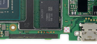
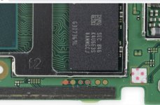
The testpads for the 4 internal UART ports are very well documented here
(in cluster C you will find UART-A which is a completely unused albeit hard to reach internal point of entry that would otherwise be perfect for our use case.)
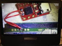
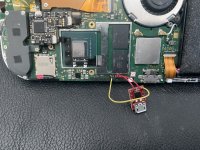
Here is a guy who tapped into the internal UART-A testpads and built a UART port permanently inside his switch.
There’s a treasure trove of Joycon reverse engineering with pinout information here
So what’s the point?
Well, I wanted the ability to temporarily hook up a UART whenever I needed to troubleshoot and the guys on #Switchroot were always talking about their joycon rail based UART logs during troubleshooting.
It couldn’t be that hard, right?
Well, it’s not hard once you’ve done one but finding all the information in one place and the final CROSS wiring (TX to RX) isn’t clear until you’ve done it wrong!
At the end of the day all you need is a USB to UART device from Amazon.
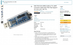
This is the one I used.
UPDATE: at the end of this thread I discovered this adapter which is a little more expensive because you have to buy 2 but it‘s MUCH smaller so it can be mounted inside the Switch to UART-A
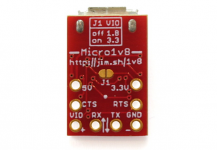
https://jim.sh/1v8/
TX, RX and GND are still the only connections you need.
Important: This UART has the ability to move a jumper to make it do 1.8V. You MUST switch the device to 1.8V or you will damage your UART port.
We need to make a simple cable to connect the USB-to-UART to an unused Joycon rail assembly.
Here are the pinouts (1-10 from Left to Right)
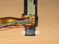
Documentation of each pin pictured above:
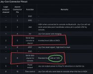
We need pins 1, 5, and 8. Notice the 1.8V requirement.
We’ll start with the “finished product”
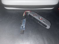
Here’s where you need to solder the 3 wires inside:
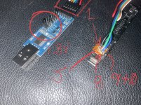
Another warning to set the jumper on the USB-to-UART circled in RED to 1.8V! If your UART can’t do 1.8V you should return it and get the correct one. If you connect a higher voltage UART you will fry your port.
1 - Black (GND)
5 - Green TX (Serial data console to Joycon)
8 - Blue RX (Serial data Joycon to console)
9 - 10 (connected with a glob of solder because this joycon doubles as an RCM Jig.)
You want to cross the TX (transmit) and RX (receive) wires with a cable to the connector in the red box at the end of the USB-to-UART adapter.
2 - Black (GND)
3 - Blue (TXD)
4 - Green (RXD)
On your PC you simply plug in your USB-to-UART device and then look in Device Manager and you should see it under Ports (COM&LPT)
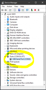
Download putty.exe for your platform from the source site here: https://www.chiark.greenend.org.uk/~sgtatham/putty/latest.html
Open putty.exe and go to Connection -> Serial and set the serial line to match the com port in Device Manager above.
In my case that was COM3.
Speed should be 115200 and then what's commonly known as 8-n-1 or eight none and one.
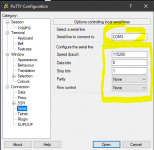
Go back to Session
On connection type tap the radio button Serial.
Be sure your Serial line says COM3 and your Speed says 115200
Once everything looks like this:
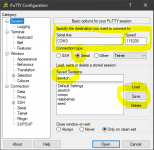
You can type in a name for Saved Session and then click Save.
Now for some money shots!
As mentioned above there are 4 UART ports available on the Switch. The right Joycon rail is UART-B which in the Atmosphere docs is Port 1.
Edit your sd:/exosphere.ini file and set the log_port=1 and log_baud_rate=115200.
(Leave log_inverted=0 unless you don’t get anylogs at which point you can try setting it to log_inverted=1 and if it works that means you need to set it back to 0 and swap your TX and RX wires and try again.)
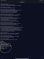
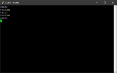
We should be all set…let’s Open our putty session, boot Atmosphere and watch the logs…
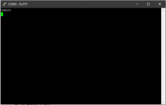
It's a bit anticlimactic because there's nothing going wrong but if there were errors they would show up here.
Let's do something a little more exciting and boot L4T from #Switchroot
Close your putty.exe window and open a new one.
This time let's configure L4T to do it’s looking on UART-B and see what happens...
The README_CONFIG.txt file for L4T says the UART port numbers are done slightly differently than Atmosphere:

0 is disabled, 1 is UART-A (the hidden unused one inside the Switch) and UART-B (the joycon rail one we are using) is port 2.
We make that change in /bootloader/ini/L4T-bionic.ini
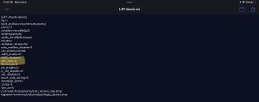
Once again we ready a putty session, and…
It's a UNIX system! I know this!
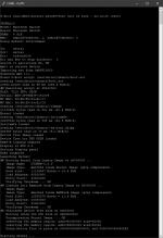
Let me know if you run into anything w/ this tut.
Happy to make adjustments...
First off, what is UART and why the heck do you want one?
Short answer is that it’s an easy way to get a console on a device and see what’s going on inside a device (such as a Switch) while it boots. So even if you can’t get to boot up, you can get some hints as to why. This is especially helpful when troubleshooting things such as Linux4Tegra and Android on Switch such as what you will find on #Switchroot
You can read more about Universal Asynchronous Receiver Transmitter here on Wikipedia.
There is great UART documentation on Switchbrew as well.
There’s documentation for UART logging in the Atmosphere config files too
# Key: log_port, default: 0. # Desc: Controls what uart port exosphere will set up for logging. # NOTE: 0 = UART-A, 1 = UART-B, 2 = UART-C, 3 = UART-D
The testpads for the 4 internal UART ports are very well documented here
(in cluster C you will find UART-A which is a completely unused albeit hard to reach internal point of entry that would otherwise be perfect for our use case.)
Here is a guy who tapped into the internal UART-A testpads and built a UART port permanently inside his switch.
There’s a treasure trove of Joycon reverse engineering with pinout information here
So what’s the point?
Well, I wanted the ability to temporarily hook up a UART whenever I needed to troubleshoot and the guys on #Switchroot were always talking about their joycon rail based UART logs during troubleshooting.
It couldn’t be that hard, right?
Well, it’s not hard once you’ve done one but finding all the information in one place and the final CROSS wiring (TX to RX) isn’t clear until you’ve done it wrong!
At the end of the day all you need is a USB to UART device from Amazon.

This is the one I used.
UPDATE: at the end of this thread I discovered this adapter which is a little more expensive because you have to buy 2 but it‘s MUCH smaller so it can be mounted inside the Switch to UART-A

https://jim.sh/1v8/
TX, RX and GND are still the only connections you need.
Important: This UART has the ability to move a jumper to make it do 1.8V. You MUST switch the device to 1.8V or you will damage your UART port.
We need to make a simple cable to connect the USB-to-UART to an unused Joycon rail assembly.
Here are the pinouts (1-10 from Left to Right)

Documentation of each pin pictured above:

We need pins 1, 5, and 8. Notice the 1.8V requirement.
We’ll start with the “finished product”

Here’s where you need to solder the 3 wires inside:

Another warning to set the jumper on the USB-to-UART circled in RED to 1.8V! If your UART can’t do 1.8V you should return it and get the correct one. If you connect a higher voltage UART you will fry your port.
1 - Black (GND)
5 - Green TX (Serial data console to Joycon)
8 - Blue RX (Serial data Joycon to console)
9 - 10 (connected with a glob of solder because this joycon doubles as an RCM Jig.)
You want to cross the TX (transmit) and RX (receive) wires with a cable to the connector in the red box at the end of the USB-to-UART adapter.
2 - Black (GND)
3 - Blue (TXD)
4 - Green (RXD)
On your PC you simply plug in your USB-to-UART device and then look in Device Manager and you should see it under Ports (COM&LPT)

Download putty.exe for your platform from the source site here: https://www.chiark.greenend.org.uk/~sgtatham/putty/latest.html
Open putty.exe and go to Connection -> Serial and set the serial line to match the com port in Device Manager above.
In my case that was COM3.
Speed should be 115200 and then what's commonly known as 8-n-1 or eight none and one.

Go back to Session
On connection type tap the radio button Serial.
Be sure your Serial line says COM3 and your Speed says 115200
Once everything looks like this:

You can type in a name for Saved Session and then click Save.
Now for some money shots!
As mentioned above there are 4 UART ports available on the Switch. The right Joycon rail is UART-B which in the Atmosphere docs is Port 1.
Edit your sd:/exosphere.ini file and set the log_port=1 and log_baud_rate=115200.
(Leave log_inverted=0 unless you don’t get anylogs at which point you can try setting it to log_inverted=1 and if it works that means you need to set it back to 0 and swap your TX and RX wires and try again.)

We should be all set…let’s Open our putty session, boot Atmosphere and watch the logs…

It's a bit anticlimactic because there's nothing going wrong but if there were errors they would show up here.
Let's do something a little more exciting and boot L4T from #Switchroot
Close your putty.exe window and open a new one.
This time let's configure L4T to do it’s looking on UART-B and see what happens...
The README_CONFIG.txt file for L4T says the UART port numbers are done slightly differently than Atmosphere:

0 is disabled, 1 is UART-A (the hidden unused one inside the Switch) and UART-B (the joycon rail one we are using) is port 2.
We make that change in /bootloader/ini/L4T-bionic.ini

Once again we ready a putty session, and…
It's a UNIX system! I know this!

Let me know if you run into anything w/ this tut.
Happy to make adjustments...
Last edited by binkinator,


