Hardware BQ24193 low VBUS input

Mightyjebus

Well-Known Member
OP
Newcomer
Joined
May 20, 2020
Messages
49
Trophies
0
Age
53
XP
257
Country
United Kingdom
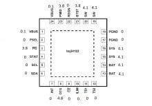
I've got a switch here that has low VBUS inputs on pins 1 and 24. I can see voltage on both pins at the USB C connector (4 and 9 showing 5V either way the charger is plugged in).

All the caps around the BQ chip don't show any shorts and most of these caps have around 4v on one side. I've swapped the BQ twice and I've swapped the fuel gauge but see no difference. The switch doesn't charge and shows 0V on the USB inline adapter.

Pin 2 shows 0v but the datasheet says high for USB source and Low for adpater. I'm not sure how the switch adapter would be classified as it's USB-C but with a 18V adapter.
.
I've attached a picture of the voltages I'm seeing on all the pins of the BQ. Any help would be very welcome.
 

Attachments

  • BQ24193 voltage.jpg
    BQ24193 voltage.jpg
    80.9 KB · Views: 821

Mightyjebus

Well-Known Member
OP
Newcomer
Joined
May 20, 2020
Messages
49
Trophies
0
Age
53
XP
257
Country
United Kingdom
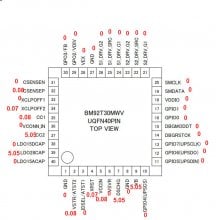
Thanks for the help Pintglass. I've attached a diagram of the voltages I'm seeing on the M92 IC. The fuse has 5v on the top side with either Nintendo or standard USB charger. I was going to share the same diagram for the P3USB chip but I get 0v on all the pins.
 

Attachments

  • M92 readings.jpg
    M92 readings.jpg
    99.7 KB · Views: 694

Pintglass

Well-Known Member
Member
Joined
Jan 28, 2019
Messages
364
Trophies
0
Age
52
XP
782
Country
United Kingdom
Thanks for the help Pintglass. I've attached a diagram of the voltages I'm seeing on the M92 IC. The fuse has 5v on the top side with either Nintendo or standard USB charger. I was going to share the same diagram for the P3USB chip but I get 0v on all the pins.

Change the M92T36 IC
 

Theorem

Well-Known Member
Newcomer
Joined
Dec 19, 2018
Messages
57
Trophies
0
XP
1,196
Country
Czech Republic
PIN 1 of BQ has to be powered (5 or 12V) from MT otherwise no charging.BQ is probably good, first target is M92
 
Last edited by Theorem,

Mightyjebus

Well-Known Member
OP
Newcomer
Joined
May 20, 2020
Messages
49
Trophies
0
Age
53
XP
257
Country
United Kingdom
I swapped M92 and the results are still 0v charging. I get different readings on the IC's now but pin 1/24 is only 1.4v which is an improvement but still short of the required 5 to 12.

Any ideas what could be dragging the voltage down?
BQ24193 after M92 change.jpg
M92 after swap.jpg
 

bombob

Well-Known Member
Newcomer
Joined
May 4, 2020
Messages
99
Trophies
0
Age
40
XP
228
Country
United States
Supposed to get at least 5v on vcc.And Make sure you are replacing them with known good ic.

Sent from my SM-N960U using Tapatalk
 
Last edited by bombob,

Mightyjebus

Well-Known Member
OP
Newcomer
Joined
May 20, 2020
Messages
49
Trophies
0
Age
53
XP
257
Country
United Kingdom
What charger are you using?

So I've been using my 5v USB inline adapter for all these results. I did use the original Nintendo charger to check the voltages on the BM IC but got the same results so thought nothing of it.

I tried the official charger again since you mentioned it and weirdly I don't get any voltage across the fuse. I still see the same voltages on pin 1/24 at 1.24v but the Nintendo charger is showing nothing across the fuse. I've swapped it 180 degrees in the charge port and get the same result of 0V across the fuse.

I know the charger is good so I'm a bit stumped why I can see a voltage at pin 1 but nothing across the fuse?
 

Ttm3

Well-Known Member
Member
Joined
May 16, 2020
Messages
248
Trophies
0
Age
43
XP
716
Country
United States
So I've been using my 5v USB inline adapter for all these results. I did use the original Nintendo charger to check the voltages on the BM IC but got the same results so thought nothing of it.

I tried the official charger again since you mentioned it and weirdly I don't get any voltage across the fuse. I still see the same voltages on pin 1/24 at 1.24v but the Nintendo charger is showing nothing across the fuse. I've swapped it 180 degrees in the charge port and get the same result of 0V across the fuse.

I know the charger is good so I'm a bit stumped why I can see a voltage at pin 1 but nothing across the fuse?

Are you getting voltage on either side of the fuse? I've had the official Nintendo charger shut down when it sees fault.
 

Mightyjebus

Well-Known Member
OP
Newcomer
Joined
May 20, 2020
Messages
49
Trophies
0
Age
53
XP
257
Country
United Kingdom
forget the problem with the Nintendo charger. I was being a moron (well my multimeter was).

I get 5v on either side of the fuse using the Nintendo charger. I also see very slight differences in the voltages going to the M92 and the BQ IC but nothing major as far as I can tell. The only changes are highlighted green in the pictures below.
BQ24193 after M92 change and nintendo charger.jpg
M92 after swap with nintendo charger.jpg


I'm doing all these tests with the battery attached. Is it worth seeing what I get on the BQ IC without the battery?
 
Last edited by Mightyjebus,

Pintglass

Well-Known Member
Member
Joined
Jan 28, 2019
Messages
364
Trophies
0
Age
52
XP
782
Country
United Kingdom
I'd forget what the BQ24193 is doing until you get the M92T36 working, you need at least 5v on pin 22 to get a higher voltage on pins 21 & 23 to turn the mosfets on. Where did you get the replacement M92T36 from.
Check all the caps around the M92T36 for shorts.
 

Theorem

Well-Known Member
Newcomer
Joined
Dec 19, 2018
Messages
57
Trophies
0
XP
1,196
Country
Czech Republic
Try to revert charging cable because according to CC1 and CC2 pins you are still using same orientation of PD charger. Check USB-C port diode values at least from top side my guess would be USB port fault - this is where it all begins and ends.
 
Last edited by Theorem,

Mightyjebus

Well-Known Member
OP
Newcomer
Joined
May 20, 2020
Messages
49
Trophies
0
Age
53
XP
257
Country
United Kingdom
So I tried a new USB C connector and got the same results. I've decided to tack a wire to the cap feeding into Pin 22 on the M92 and try and trace where it goes. So far I've done the A side of the board and found a few places with continuity. I will turn the board over and do the same. Obviously I can't check the underside of BGA IC's but it might be enough to try and find the voltage drop going to Pin 22.

In the picture below you can see where I get continuity to Pin 22 on the A side of the board (Board is 010 version so will be different to other revisions {please ignore flux as this will be cleaned up shortly})
pin 22 M92.jpg


Out of curiosity anyone know what the 3 lots of 6 pin IC's are below the M92?
 

Theorem

Well-Known Member
Newcomer
Joined
Dec 19, 2018
Messages
57
Trophies
0
XP
1,196
Country
Czech Republic
These are mosfets used for switching voltage - two single channels (lower ones) and one dual (closer to MT). From the provided picture i cant judge MT92 soldering but at least some parts of it looks a bit suspicious. Could you IPA it and provide better resolution snap ?
 

Mightyjebus

Well-Known Member
OP
Newcomer
Joined
May 20, 2020
Messages
49
Trophies
0
Age
53
XP
257
Country
United Kingdom
I'll try to sort out a better picture of the M92 but in the mean time this is where I'm at.
I removed the small cap bwteen the Mosfets to see if I loose connection to pin 22 on the m92 and I do so it looks like M92 pin 22 is directly connected to this pad.
With a 5v USB inline adapter I still get OA charging but I did a diagram which is attached below to show what I'm seeing. If the 6 pin IC's are for switching power then the last pin on each go somewhere by Via's and I'll need to figure out where they go as it looks like they aren't receiving the correct signal to switch either the 5v from the fuse side or the 1.4v from the BQ pin 1.
Drawing1.jpg

The red points all have continuity to Pin 22 on the M92 but this goes if I remove the little cap which is showing 0.12v in the diagram.
The yellow points are the 2 Via's which I'll try and trace next.
 

Mightyjebus

Well-Known Member
OP
Newcomer
Joined
May 20, 2020
Messages
49
Trophies
0
Age
53
XP
257
Country
United Kingdom
good news and bad news. I figured out why I wasn't getting any ampage when plugging in the charger. I replaced the BQ chip again as I wasn't happy with the 1.4V on Pin 1/24 feeding up to the mosfets. As soon as I did that I got 0.4A charging but no swap to fast charging or anything on the screen. So it looks like it's a 5v 0.4A non-booting switch. I've got some reballing bits and pieces coming from China so I might revisit this one then.
Until then I now know if I get a bad voltage out of Pin 1 on the BQ then best bet would be to swap it out.

Thanks for all your help.
 

Pintglass

Well-Known Member
Member
Joined
Jan 28, 2019
Messages
364
Trophies
0
Age
52
XP
782
Country
United Kingdom
good news and bad news. I figured out why I wasn't getting any ampage when plugging in the charger. I replaced the BQ chip again as I wasn't happy with the 1.4V on Pin 1/24 feeding up to the mosfets. As soon as I did that I got 0.4A charging but no swap to fast charging or anything on the screen. So it looks like it's a 5v 0.4A non-booting switch. I've got some reballing bits and pieces coming from China so I might revisit this one then.
Until then I now know if I get a bad voltage out of Pin 1 on the BQ then best bet would be to swap it out.

Thanks for all your help.

Pin 1/24 on BQ24193 is power in, which comes from the M92T36 turning on the mosfets, you must of had something shorted on the BQ24193 that was pulling it down.
 

Site & Scene News

Popular threads in this forum

Recent Content

General chit-chat
Help Users
  • No one is chatting at the moment.
    Xdqwerty @ Xdqwerty: good night