

Hacking Trinket M0 installed inside the switch
- Thread starter fishburn1080
- Start date
- Views 16,332
- Replies 33


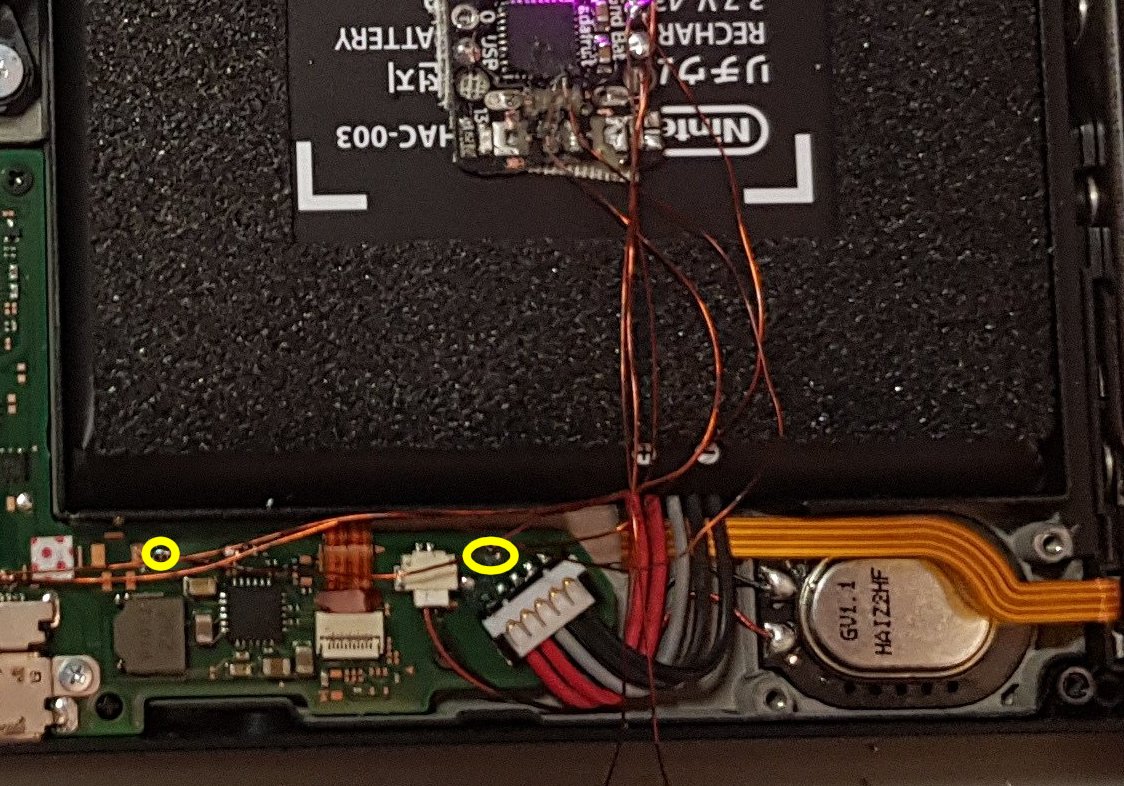
![20180614_142429[1].jpg](https://gbatemp.net/data/attachments/132/132088-0ee7da240f93bf999f90830c01194379.jpg?hash=DufaJA-Tv5 "20180614_142429[1].jpg")
![20180614_142608[1].jpg](https://gbatemp.net/data/attachments/132/132089-0e302f967d1b0ab78fa49efc68262b05.jpg?hash=DjAvln0bCr "20180614_142608[1].jpg")


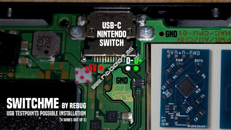
") that could work with the supply.
that could work with the supply.
Similar threads
Site & Scene News
New Hot Discussed
-
-
26K views
Sony is moving away from physical discs, will soon only release PlayStation games digitally
Sony made a shocking announcement today, revealing that the company plans to move away from physical game releases in the future. Citing claims of how the industry is... -
13K views
Xbox to increase in price again in August, Series S set to hit $500
Remember when you could get an Xbox Series S for $300? Those were the days. Microsoft has today announced the latest in their console price hikes, seeing their... -
12K views
Grand Theft Auto VI pre orders go live tomorrow, physical release limited to code in box
The delays may be behind us, but the news isn't all good for Grand Theft Auto VI. Rockstar have today announced that pre-orders for the game will go live tomorrow, on... -
9K views
Nintendo announces plans to discontinue Nintendo Switch line in Europe next year, outlines upcoming hardware changes for other devices
Last month we got confirmation of a new model of Switch 2 to better comply with upcoming EU regulations. With the legislation set to come into effect in February of... -
7K views
Sony announces shutdown of the PlayStation Store for the PS3 and Vita
The end has come for the PlayStation 3 and the PlayStation Vita. After supporting the PSN Store on the PS3 and PS Vita since 2006 and 2011 respectively, Sony has... -
5K views
A multi-platform port for Pokemon Emerald is in the works, supports Windows, Linux, and Android
Tired of waiting for Game Freak to bring Pokemon Emerald to modern platforms? We've got you covered with a brand new port in the works. Currently available on GitHub... -
5K views
Steam Summer Sale goes live, various titles discounted by varied amounts
In this time of economic uncertainty and rampant price hikes, the Steam sales stand as our final bastions of affordability for those opting to avoid the seas. The... -
5K views
Apple raises prices on MacBook and iPad lines, MacBook Neo starting price increased by $100
Apple have today announced price increases, primarily focused on their MacBook and iPad lines. These increases have already come into effect, with both prices and the... -
4K views
ROM Hack Pokemon Timeless Diamond and Spaceless Pearl released, enhances original Sinnoh releases with quality of life changes and new events
For fans of Sinnoh, the pickings are slim. If you want the best experience you're left deciding between the updated region in Platinum, or the somewhat controversial... -
4K views
Homebrew app PS2 emulator NetherSX2 gets a Switch port
The Switch 2 has been out for a year now, but you shouldn't count the original system out yet! Released a few days ago, popular PS2 emulator NetherSX2 has found its...
-
-
-
399 replies
Sony is moving away from physical discs, will soon only release PlayStation games digitally
Sony made a shocking announcement today, revealing that the company plans to move away from physical game releases in the future. Citing claims of how the industry is... -
159 replies
Xbox to increase in price again in August, Series S set to hit $500
Remember when you could get an Xbox Series S for $300? Those were the days. Microsoft has today announced the latest in their console price hikes, seeing their... -
149 replies
Grand Theft Auto VI pre orders go live tomorrow, physical release limited to code in box
The delays may be behind us, but the news isn't all good for Grand Theft Auto VI. Rockstar have today announced that pre-orders for the game will go live tomorrow, on... -
75 replies
Nintendo announces plans to discontinue Nintendo Switch line in Europe next year, outlines upcoming hardware changes for other devices
Last month we got confirmation of a new model of Switch 2 to better comply with upcoming EU regulations. With the legislation set to come into effect in February of... -
64 replies
Sony announces shutdown of the PlayStation Store for the PS3 and Vita
The end has come for the PlayStation 3 and the PlayStation Vita. After supporting the PSN Store on the PS3 and PS Vita since 2006 and 2011 respectively, Sony has... -
55 replies
A multi-platform port for Pokemon Emerald is in the works, supports Windows, Linux, and Android
Tired of waiting for Game Freak to bring Pokemon Emerald to modern platforms? We've got you covered with a brand new port in the works. Currently available on GitHub... -
43 replies
ROM Hack Ocarina of Time 3D gets huge mod to enable single-screen play
Ocarina of Time is back in style as the upcoming Switch 2 remake looms on the horizon. But what's a fan of the game to do over the next few months? If you've been... -
42 replies
Apple raises prices on MacBook and iPad lines, MacBook Neo starting price increased by $100
Apple have today announced price increases, primarily focused on their MacBook and iPad lines. These increases have already come into effect, with both prices and the... -
38 replies
Steam Summer Sale goes live, various titles discounted by varied amounts
In this time of economic uncertainty and rampant price hikes, the Steam sales stand as our final bastions of affordability for those opting to avoid the seas. The... -
37 replies
Remasters for Fallout 3 and New Vegas announced, Fallout 5 still in development
Amidst news of layoffs and cancellations in the wake of Xbox's larger changes, Bethesda has today come out with a statement discussing their active projects. In this...
-


