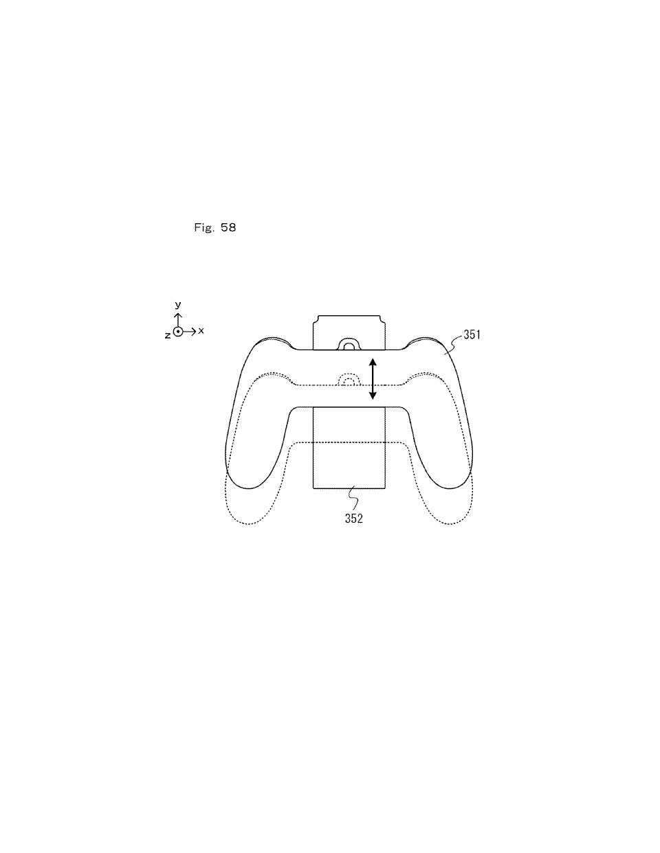
[0766] In other embodiments, the extension grip 350 may be configured so that the main section 351 can be attached to the support section 352 at a plurality of different positions with respect to the up-down direction. For example, screw holes may be provided on the reverse surface of the support section 352 at a plurality of different positions in the up-down direction, so that the main section 351 can be attached to the support section 352 by screwing a screw in one of the screw holes.
[0767] As described above, the extension grip 350 may be configured so that the distance in the up-down direction between a grip portion of the main section 351 and a controller attached to the support section 352 is variable. Then, it is possible to adjust the distance to an appropriate distance for each user (e.g., to a distance suitable for the size of the hands of the user, etc.), thus improving the controllability of the extension grip 350.
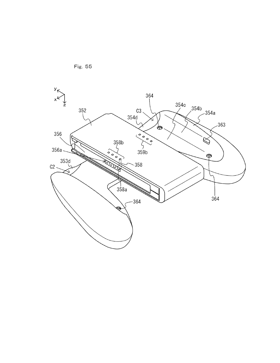
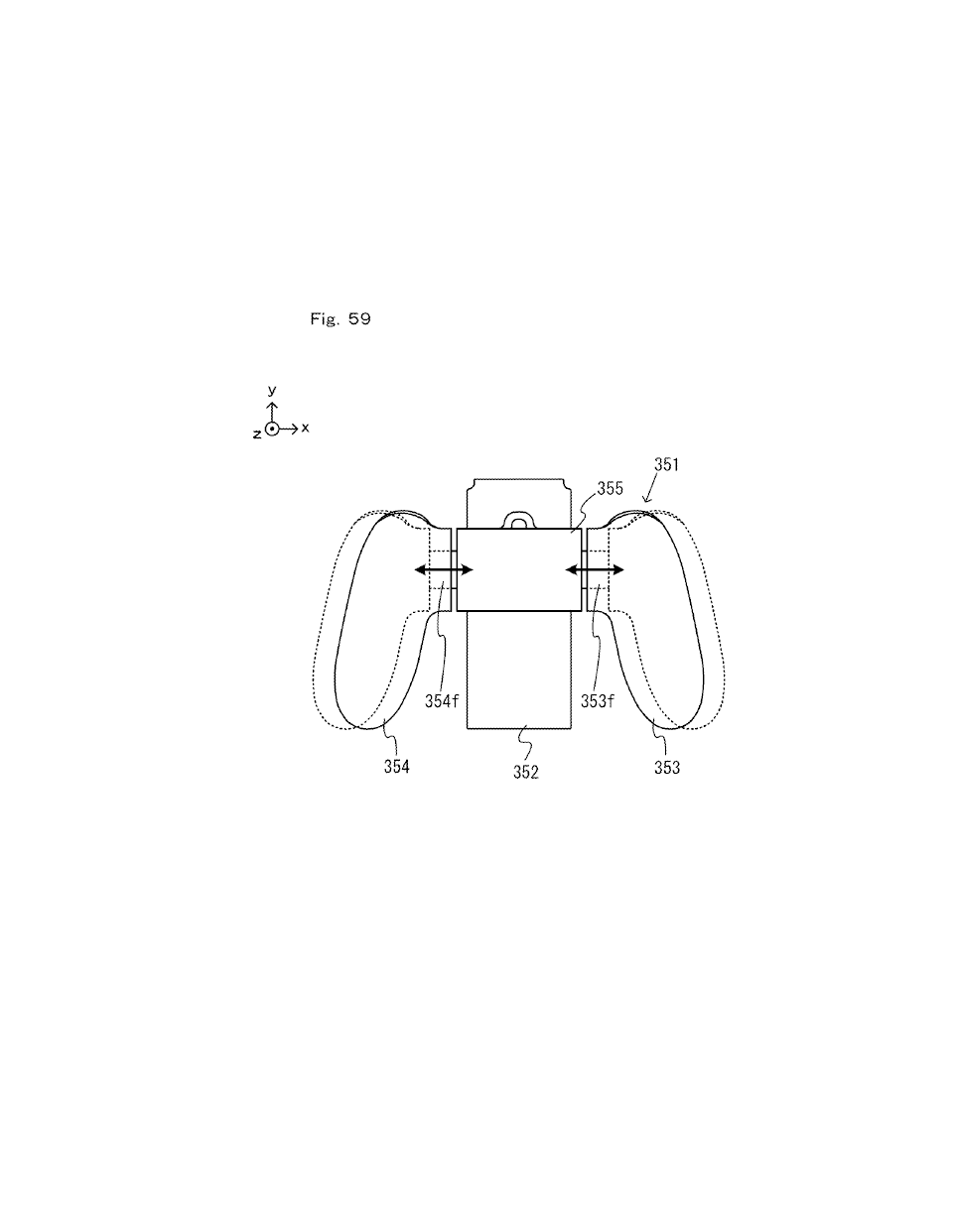
[0768] In other embodiments, with the extension grip 350 shown in FIG. 55, the distance between a grip portion and a controller attached to the extension grip 350 (in other words, the rail member of the extension grip 350) may be variable. FIG. 59 is a diagram showing an example configuration of an extension grip in which the distance between a grip portion and a controller is variable. As shown in FIG. 59, the grip portions 353 and 354 may be movable in the left-right direction (i.e., the x-axis direction) in the main section 351. That is, the connection portion 355 may be connected to the grip portions 353 and 354 so as to be movable in the left-right direction. Note that it can be said that with the configuration shown in FIG. 59, the distance between the left and right grip portions 353 and 354 is variable.
[0769] There is no particular limitation on the mechanism that allows the grip portions 353 and 354 to be movable. For example, the connection portion 355 and the grip portions may be connected to each other by a slide mechanism that can slide in the left-right direction (in other words, the direction in which the interval between the connection portion and the grip portions is varied).
[0770] Specifically, as shown in FIG. 59, the left grip portion 353 may include an arm 353f and the right grip portion 354 may include an arm 354f The arms 353f and 354f are inserted into holes (not shown) provided on the left and right side surfaces of the connection portion 355, and are connected so as to be slidable in the left-right direction with respect to the connection portion 355. Then, the connection portion 355 includes a mechanism for limiting (in other words, locking) the slide movement of the grip portions 353 and 354 at a plurality of positions (which may be any positions) within the range of slide movement of the grip portions 353 and 354. Although not shown in the figure, for example, the connection portion 355 may include a mechanism for allowing the grip portions to slide with respect to the connection portion 355 by loosening a screw, while preventing the grip portions from sliding with respect to the connection portion 355 by tightening the screw. For example, one of the connection portion 355 and the grip portions may include a stop member capable of engaging with the other one of the connection portion 355 and the grip portions at a plurality of positions within the range of slide movement.
[0771] In other embodiments, the connection portion 355 may be configured to be stretchable in the left-right direction. That is, the connection portion 355 may include a mechanism that makes variable the length of the connection portion 355 in the left-right direction.
[0772] As described above, the extension grip 350 may include a mechanism capable of varying the distance between controllers attached thereto and the grip portions (in other words, the interval between the two grip portions 353 and 354). Then, it is possible to adjust the distance between controllers attached to the extension grip 350 and the grip portions to an appropriate distance for each user (e.g., to a distance suitable for the size of the hands of the user, etc.), thus improving the controllability of the extension grip 350.
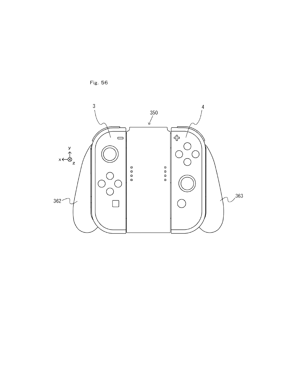
[0773] With the extension grip 350, as with the extension grip 210 shown in FIG. 52, the controllers 3 and 4 can be used while they are attached to the extension grip 350. Then, it is possible to perform operations while fixing the positional relationship between the two controllers 3 and 4, and it is therefore possible to improve the controllability of the two controllers 3 and 4 when removed from the main unit 2.
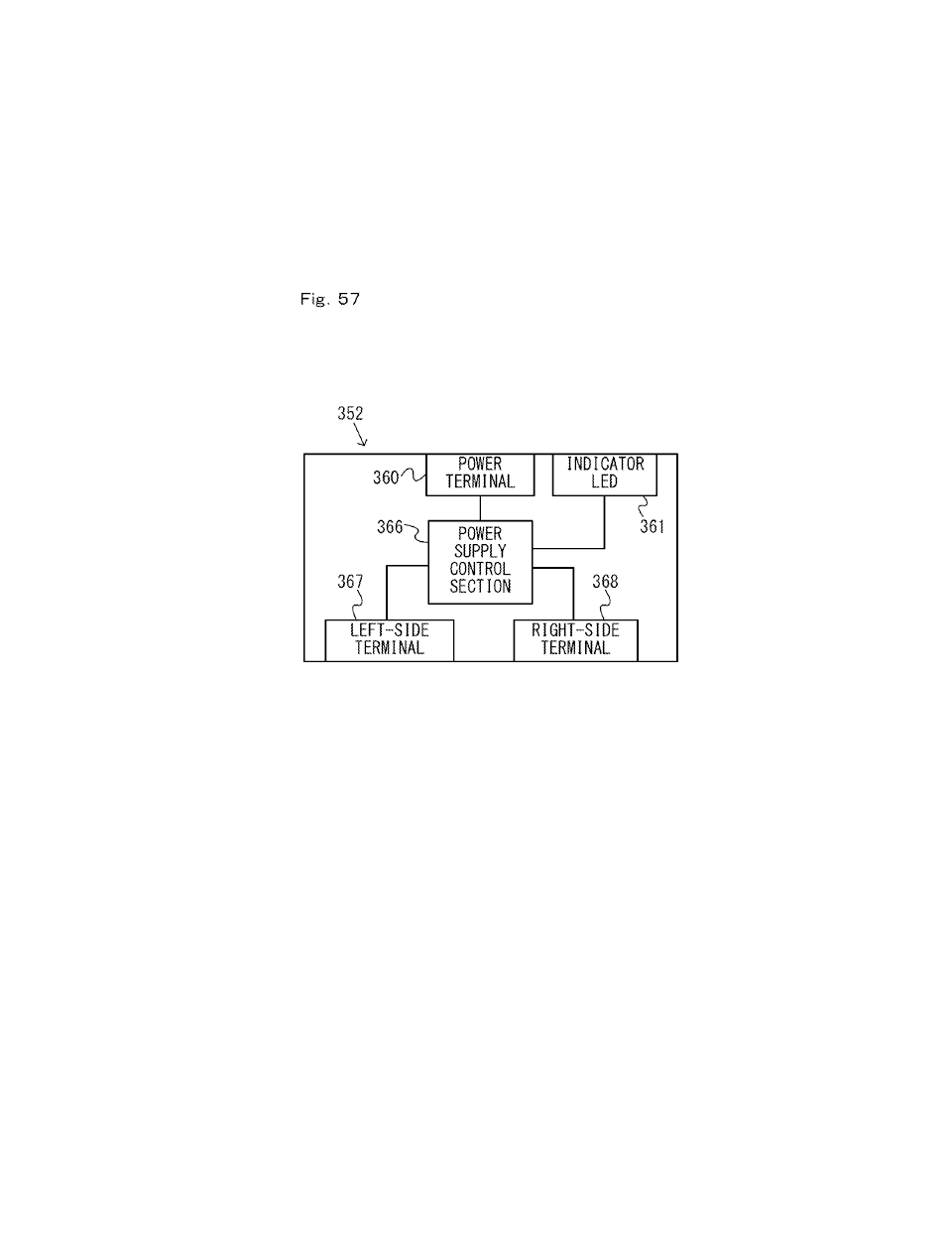
[0774] The extension grip 350 described above can be used as a charging device for the controllers. For example, when the battery of a controller has run out when the controller is used while removed from the main unit 2, a user can attach the controller to the extension grip 350 with an AC adaptor, etc., connected to the power terminal 360 thereof to charge the controller.
[0775] Note that a slide member similar to the rail member described above (i.e., the left rail member 300, etc.) may be provided on a charging device used for the purpose of charging controllers connected thereto, as well as the extension grip 350 used for the purpose of operating controllers connected thereto. Then, the charging device may include one rail member or may include a plurality of rail members so as to simultaneously charge a plurality of controllers. With charging devices, as opposed to the main unit 2 and extension grips, the rail members do not need to be provided at positions in left-right symmetry.
[0776] [5-3. Accessory for Main Unit]
[0777] The information processing system may include an accessory to which the main unit 2 can be attached. An HMD accessory to be described below as an example accessory can be used as a so-called HMD (head mounted display) with the main unit 2 attached thereto.
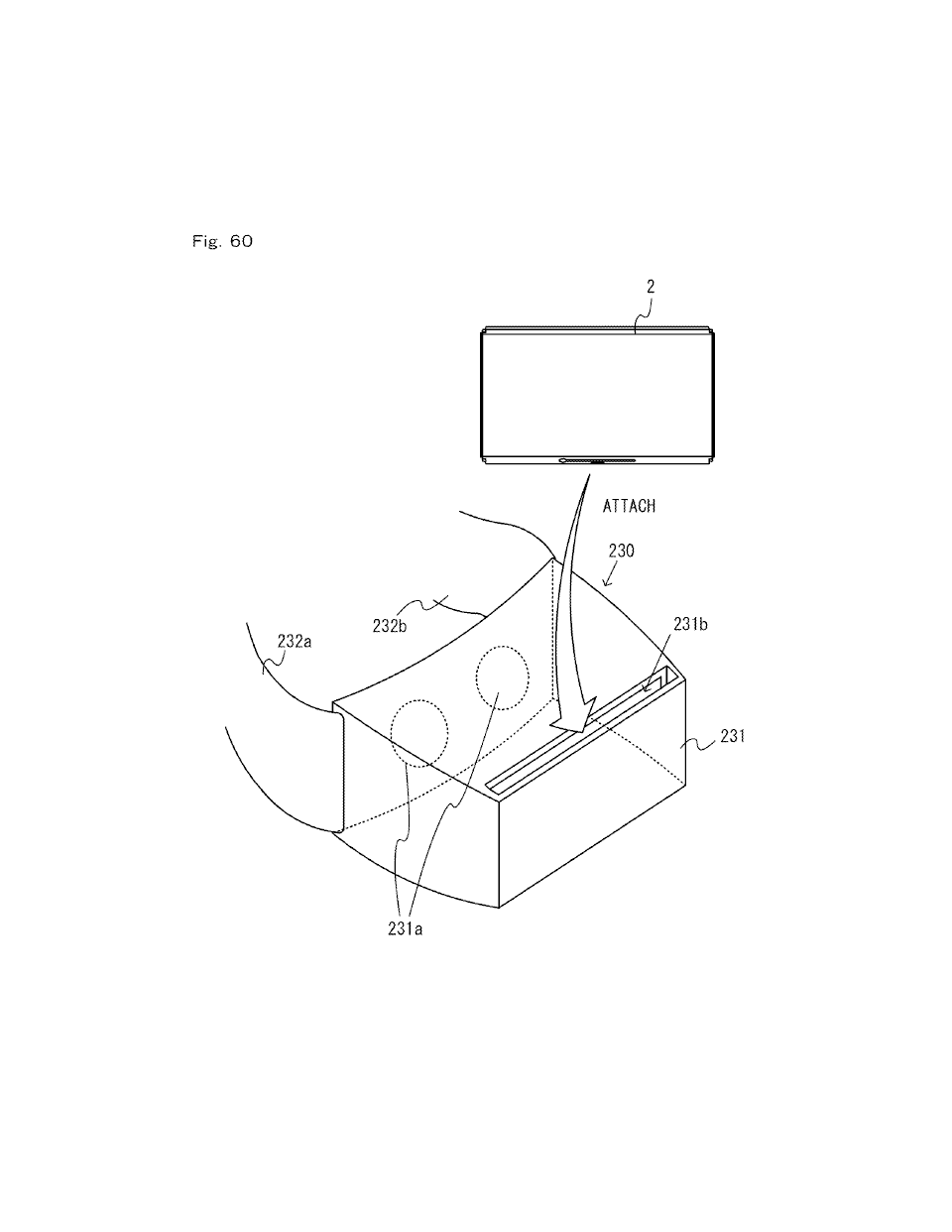
[0778] FIG. 60 is a diagram showing an example HMD accessory to which the main unit 2 can be attached. An HMD accessory 230 shown in FIG. 60 includes a housing 231 and belts 232a and 232b. One end of the belt 232a is attached to one end of the housing 231, and one end of the belt 232b is attached to the other end of the housing 231. Although not shown in the figure, the other end of the belt 232a can be removably connected to the other end of the belt 232b. Thus, the housing 231 can be mounted on the head of the user by connecting together the two belts 232a and 232b around the head of the user. Note that there is no particular limitation on the mechanism for allowing the HMD accessory 230 to be mounted on the head of the user.
[0779] As shown in FIG. 60, the housing 231 includes two openings 231a. The openings 231a are located so as to face the eyes of the user with the housing 231 mounted on the head of the user. Although not shown in the figure, the HMD accessory 230 includes a lens provided in each of the openings 231a.
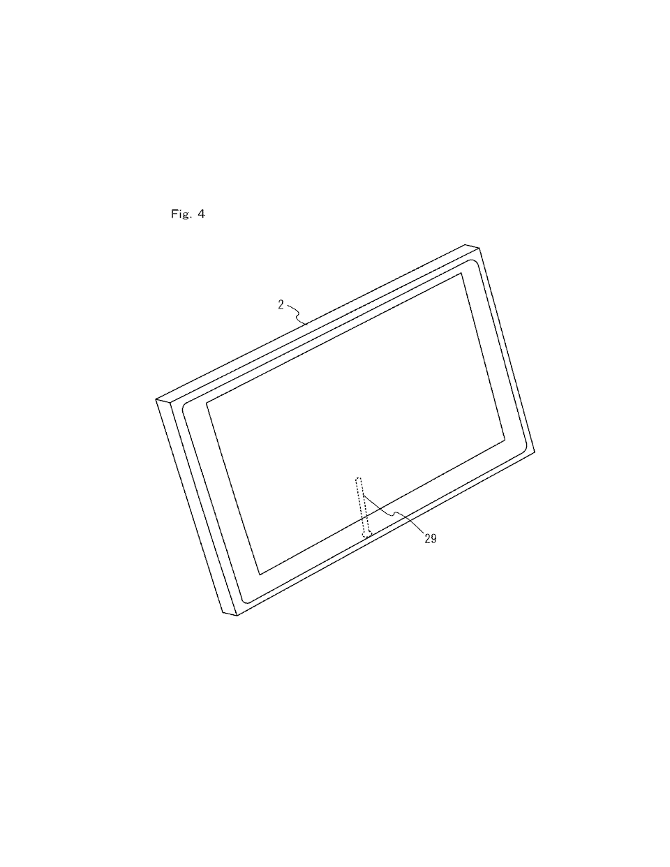
[0780] Moreover, as shown in FIG. 60, the housing 231 includes an insertion slot 231b for receiving the main unit 2 attached thereto (or inserted thereinto). That is, the main unit 2 can be attached to the HMD accessory 230 by inserting the main unit 2 into the insertion slot 231b. If the main unit 2 is attached so that the display 12 is facing the openings 231a, the display 12 can be viewed through the lenses through the openings 231a. That is, the housing 231 supports the display 12 so that the user can view the display 12 of the main unit 2.
[0781] With such a configuration, a user can view images on the display 12 when the HMD accessory 230 with the main unit 2 attached thereto is mounted on the head of the user. That is, the HMD accessory 230 with the main unit 2 attached thereto functions as a so-called HMD. Note that the HMD accessory 230 may present images of a wide viewing angle to a user by enlarging the viewing angle of the images on the display 12 through the lenses. This can enhance the sense of immersion for a user looking at the images. Note that the main unit 2 may perform a predetermined conversion process on the images displayed on the display 12 so that appropriate images are viewed through the lenses.
[0782] Note that in the present embodiment, the main unit 2 includes the acceleration sensor 89 and the angular velocity sensor 90, and can calculate the movement and/or the attitude of the main unit 2 based on the detection results of these sensors. Therefore, the main unit 2 can calculate the movement and/or the attitude of the HMD accessory 230 to which the main unit 2 is attached, and perform a predetermined process in accordance with the movement and/or the attitude. Note that the predetermined process, for example, is a process of controlling a virtual camera for producing images to be displayed on the display 12 based on the movement and/or the attitude of the HMD accessory 230, and more specifically is a process of changing the line-of-sight direction of the virtual camera depending on the attitude, for example.
[0783] In other embodiments, if the main unit 2 does not have sensors for sensing the movement and/or the attitude of the main unit 2 (e.g., an acceleration sensor and/or an angular velocity sensor), the HMD accessory 230 may include the sensors. Then, the HMD accessory 230 may transmit the detection results of the sensors (or information obtained by performing a predetermined process on the detection results) to the main unit 2. The main unit 2 may calculate the movement and/or the attitude of the HMD accessory 230 based on the information transmitted from the HMD accessory 230.
[0784] In the present embodiment, the controllers 3 and 4 may be used while they are removed from the main unit 2. Therefore, even with the main unit 2 attached to the HMD accessory 230, the controllers 3 and 4 can be used as controller devices. That is, a user can operate the controllers using the hands while the HMD accessory 230 with the main unit 2 attached thereto is mounted on the head of the user.
[0785] As described above, the information processing device 1 of the present embodiment, with the use of the HMD accessory 230 described above, can be used in a mode in which it is used as an HMD. In the present embodiment, since the controllers can be removed from the main unit 2, it is possible to reduce the weight of the device or devices to be mounted on the head of the user. A user can perform operations using removed controllers.
[0786] [6. Functions/Effects and Variations of Present Embodiment]
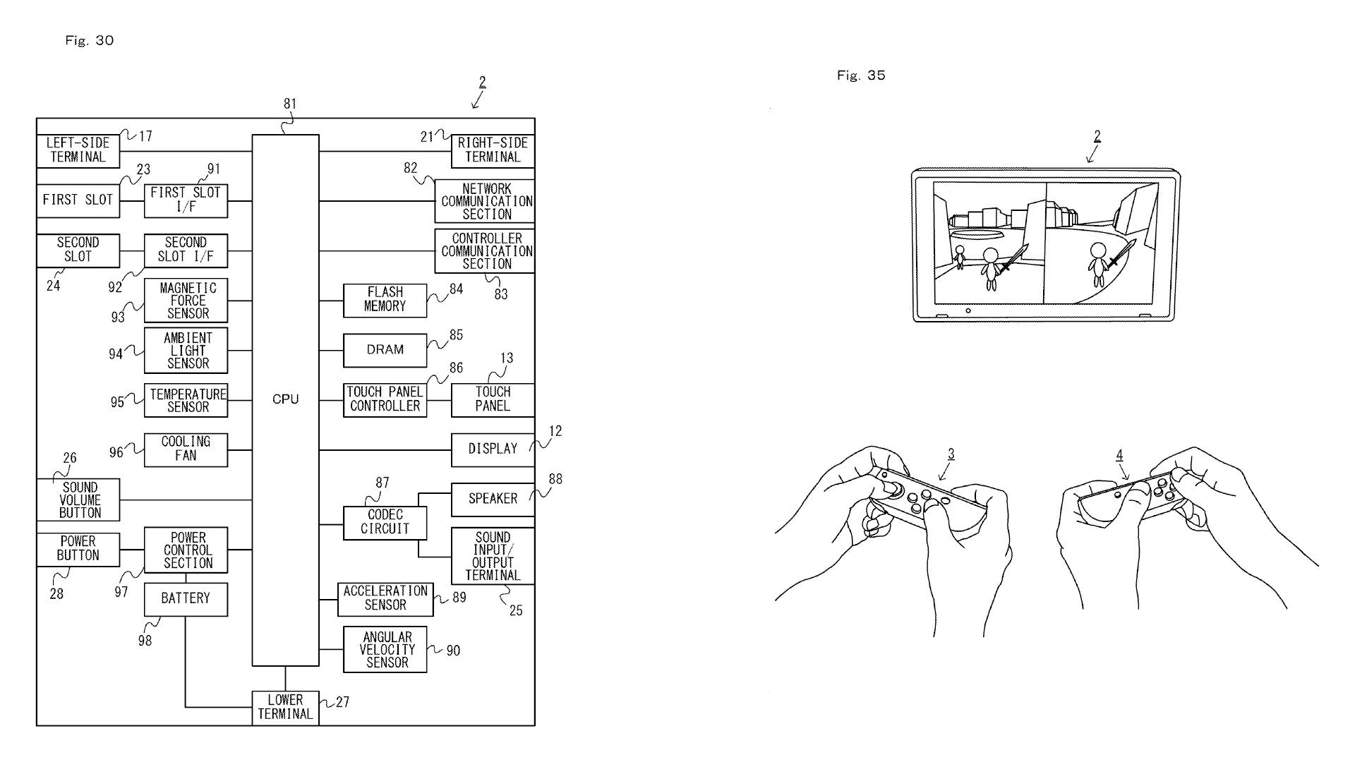
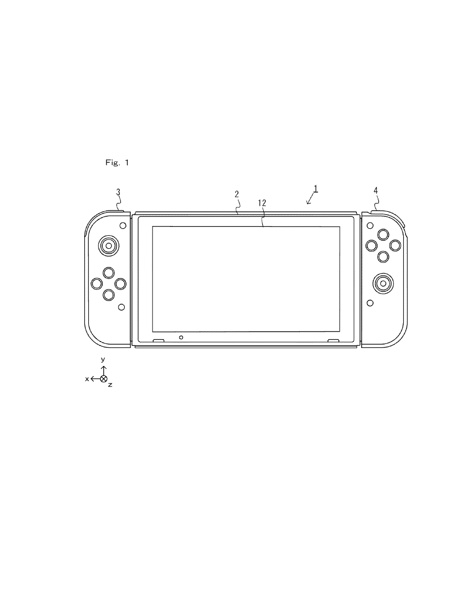
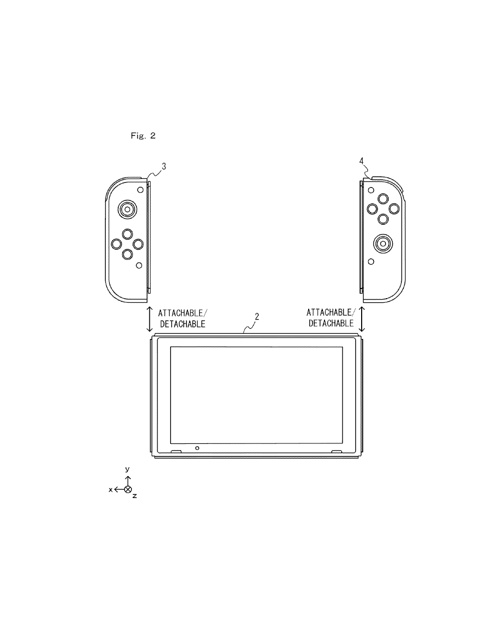
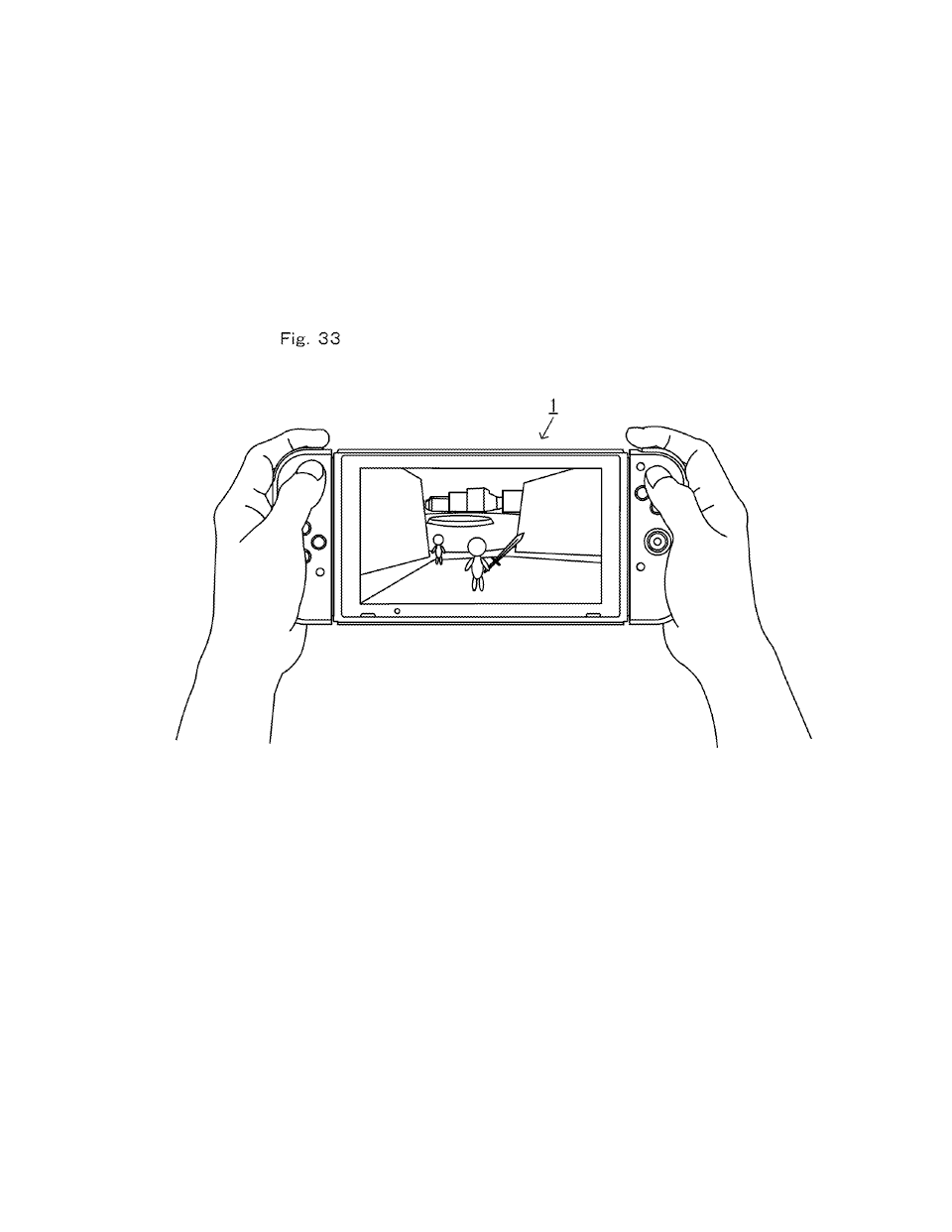
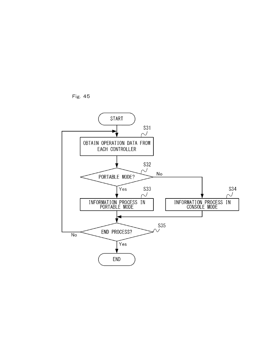
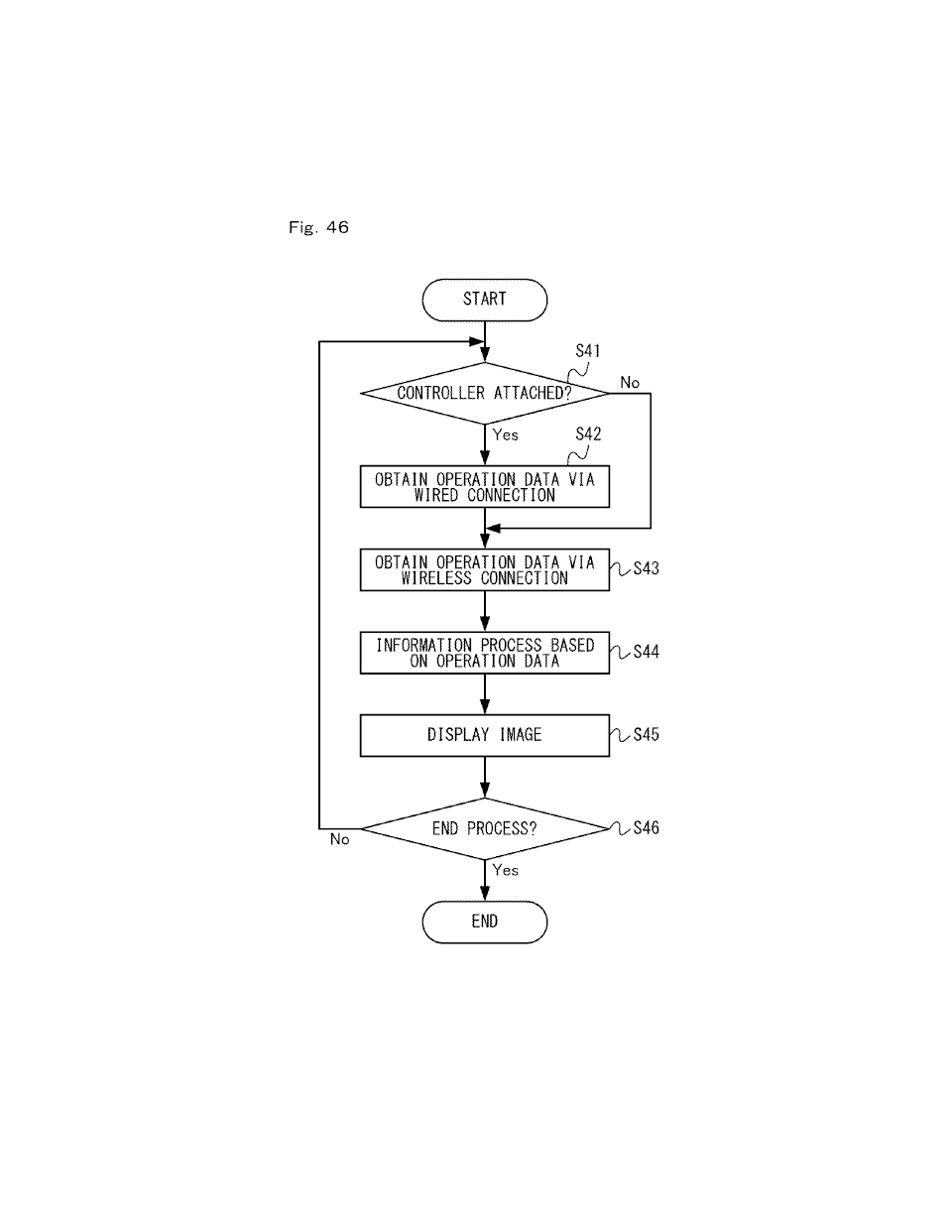
[0787] In the present embodiment described above, the information processing device 1 includes the main unit 2, the left controller (referred to also as the first controller device) 3, and the right controller (referred to also as the second controller device) 4. Since the information processing device 1 includes a plurality of devices, it can be referred to also as an information processing system. The main unit includes a display (i.e., the display 12). The left controller 3 can be attached to and detached from the main unit 2, and the right controller 4 can be attached to and detached from the main unit 2 (FIG. 2). The left controller 3 transmits first operation data representing an operation performed on the left controller 3 to the main unit 2, whether it is attached to the main unit 2 or not. The right controller 4 transmits second operation data representing an operation performed on the right controller 4 to the main unit 2, whether it is attached to the main unit 2 or not. The main unit displays, on the display, the execution result of a predetermined information process (step S44) based on the first operation data transmitted from the left controller 3 and the second operation data transmitted from the right controller 4 (step S45). Thus, with the left controller 3 and the right controller 4 attached to the main unit 2, the main unit 2 is capable of displaying, on the display, images based on operations performed on the left controller 3 and the right controller 4 (FIG. 33). The main unit 2 is also capable of displaying, on the display, images based on operations performed on the left controller 3 and the right controller 4 when the left controller 3 and the right controller 4 are removed from the main unit 2 (FIG. 34).
[0788] As described above, the information processing device 1 can be used both in the mode in which the controllers 3 and 4 are attached to the main unit 2 and in the mode in which the controllers 3 and 4 are removed from the main unit. Thus, since a plurality of modes of use are realized with a single information processing device 1, the information processing device 1 can be used in a wider variety of manners.
[0789] The "image based on operations" may be images obtained by an information process that is performed based on an operation (e.g., images obtained by an operation performed on an application used for obtaining and viewing information from the Internet) or images produced by an information process that is performed based on an operation (e.g., game images produced in accordance with a game operation performed on a game application).
[0790] In the above description, the main unit 2 may be used in the mode in which the left controller 3 and the right controller 4 are attached to the main unit 2 and in the mode in which the left controller 3 and the right controller 4 are removed from the main unit 2, and it is not necessary that both of these modes be available under certain conditions. For example, only one of the two modes may be available in a predetermined application running on the main unit 2. That is, the main unit 2 may run an application that is available only in the mode in which the left controller 3 and the right controller 4 are attached to the main unit 2, and may run another application that is available only in the mode in which the left controller 3 and the right controller 4 are removed from the main unit 2.
[0791] In the above description, the main unit 2 may include an information processing unit (e.g., the CPU 81) instead of a display.
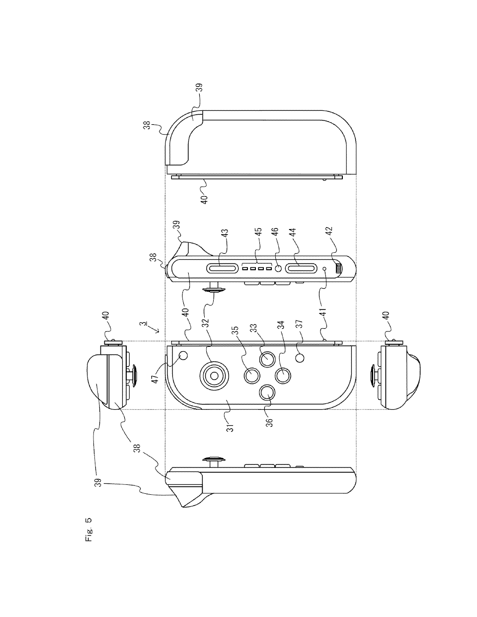
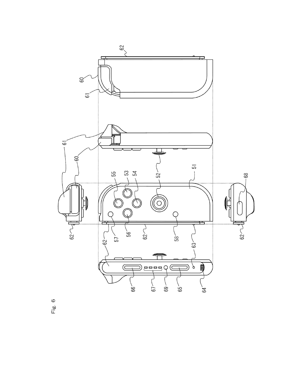
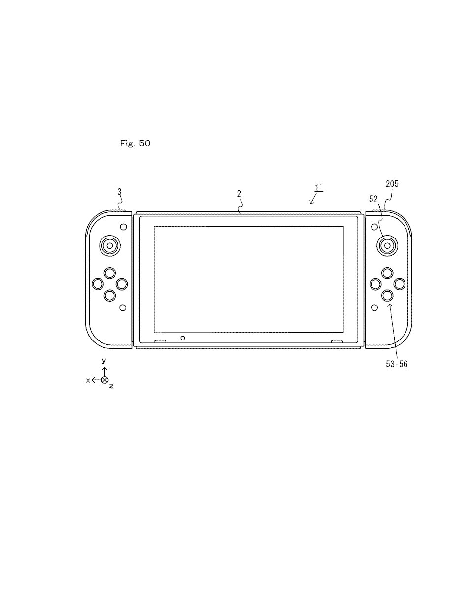
[0792] The left controller 3 includes a first input section (e.g., the analog stick 32) and a second input section (e.g., the operation buttons 33 to 36). The right controller 4 includes a third input section (e.g., the analog stick 52) of the same type as the first input section and a fourth input section (e.g., the operation buttons 53 to 56) of the same type as the second input section.
[0793] Note that an "input section" is any means that outputs information representing a user input and/or information with which it is possible to calculate (or estimate) a user input. For example, an input section may be a button, a directional input section such as an analog stick, a touch panel, a microphone, a camera, a sensor capable of calculating the movement of the controller, for example, (e.g., an acceleration sensor and an angular velocity sensor), and the like.
[0794] As described above, the left controller 3 and the right controller 4 include two sets of input sections of the same type. Therefore, using the input sections described above, a user can use two controllers in a similar manner. For example, if a single user uses a controller, it is convenient because the user can perform operations in a similar manner using either one of two controllers. Also conveniently, two users can each use one controller, for example.
[0795] In the above description, "input sections being of the same type" is not limited to cases in which the two input sections are the same input sections, but may also include cases in which two input sections have functions and/or applications of the same type. For example, if the first input section is an analog stick that can be tilted up, down, left and right, the third input section may be a slide stick that can be slid up, down, left and right or a cross-shaped key capable of making an input of up, down, left and right.
[0796] In the embodiment described above, the input mechanism of the first input section and the input mechanism of the third input section (e.g., the operation button 33 and the operation button 53 or the analog stick 32 and the analog stick 52) are substantially the same. The input mechanism of the second input section and the input mechanism of the fourth input section are substantially the same. Thus, the two controllers will have two types of input sections that can be operated in a similar fashion. Therefore, a user can use two controllers in a similar fashion, thereby improving the controllability of the controllers.
[0797] In the embodiment described above, the first input section has substantially the same shape as the third input section. Also, the second input section has substantially the same shape as the fourth input section. Thus, the two controllers will have two types of input sections that can be operated in a similar fashion. Therefore, a user can use two controllers in a similar fashion, thereby improving the controllability of the controllers.
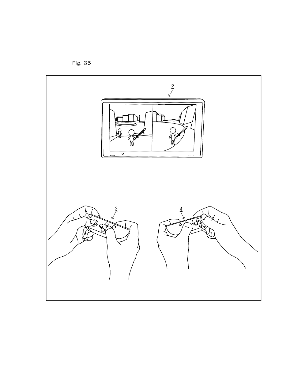
[0798] If the left controller 3 and the right controller 4 are removed from the main unit 2, the positional relationship between the first input section and the second input section of the left controller 3 placed in a certain orientation is the same as the positional relationship between the third input section and the fourth input section of the right controller 4 placed in a certain orientation. For example, consider a case in which the left side surface the left controller 3 is facing a user and the right side surface of the right controller 4 is facing another user, as shown in FIG. 35 and FIG. 37. Then, the positional relationship between the first input section (i.e., the analog stick 32) and the second input section (i.e., the operation buttons 33 to 36) is the same as the positional relationship between the third input section (i.e., the analog stick 52) and the fourth input section (i.e., the operation buttons 53 to 56).
[0799] Then, users can use the left controller 3 and the right controller 4 in a similar fashion. Thus, it is possible to improve the controllability of the controllers. For example, in the example shown in FIG. 35, with either one of the two controllers, a user can operate the analog stick with the left hand and the operation buttons with the right hand.
[0800] With the left controller 3 and the right controller 4 attached to the main unit 2, the positional relationship between the first input section (i.e., the analog stick 32) and the second input section (i.e., the operation buttons 33 to 36) is opposite from the positional relationship between the third input section (i.e., the analog stick 52) and the fourth input section (i.e., the operation buttons 53 to 56) (see FIG. 1).
[0801] Thus, if the controllers 3 and 4 are attached to the main unit 2, if a user holds the controllers 3 and 4 respectively with the left hand and the right hand, the user is allowed to easily operate different input sections with the left hand and with the right hand. Thus, it is possible to improve the controllability of the information processing device 1 with controllers attached thereto.
[0802] Now, assume a configuration in which the positional relationship between the first input section and the second input section is the same as the positional relationship between the third input section and the fourth input section. Even with such a configuration, a user may tend to operate the left and right controllers in a similar fashion (e.g., operating the analog stick with the left hand and the operation buttons with the right hand). Then, if the controllers have a similar shape to that of the present embodiment (i.e., one side surface is rounded), one controller will be held with the rounded side surface facing away from the user while the other controller will be held with the rounded side surface facing toward the user. That is, this configuration has a problem in that when users hold controllers removed from the main unit 2, the direction of the rounded side surface of one controller will be opposite to that of the other controller, which makes it less easy for a user to understand the appropriate orientation in which to hold a controller.
[0803] Moreover, with such a configuration, if sub-buttons (the second L button and/or the second R button in the embodiment described above) are provided on each controller, the sub-buttons will be provided on the rounded side surface (as in the present embodiment) for one controller, whereas the sub-buttons will be provided on the opposite side surface from the rounded side surface for the other controller. With such a configuration, however, the sub-buttons of one controller will be exposed even when the controller is attached to the main unit 2, and the sub-buttons may possibly be operated in error in the attached state.
[0804] In contrast, according to the present embodiment employing a configuration in which the positional relationship between the first input section and the second input section is opposite from the positional relationship between the third input section and the fourth input section, it is possible to prevent the two problems described above.
[0805] In the embodiment described above, the first input section and the third input section are each a directional input section for receiving a directional input. More specifically, the directional input section may include an operation member (e.g., a stick member) that can be tilted or slid in a predetermined direction. Then, a user can make directional inputs by using the left controller 3 or the right controller 4.
[0806] In the embodiment described above, the second input section and the fourth input section are each a button that can be pressed. Thus, a user can make button inputs by using the left controller 3 or the right controller 4.
[0807] In the embodiment described above, a controller is attached integrally to the main unit 2 with a surface of the housing of the controller (e.g., the right side surface for the left controller 3) facing a surface of the main unit 2 (see FIG. 2). Thus, with the controller attached to the main unit 2, a user can handle the controller and the main unit as an integral unit, thereby improving the controllability.
[0808] In the embodiment described above, the left controller 3 is attached to the main unit 2 so as to be facing one of a left side surface and a right side surface of the main unit 2 (specifically, the left side surface). The right controller 4 is attached to the main unit 2 so as to be facing the other one of the left side surface and the right side surface of the main unit 2 (i.e., the right side surface). Then, a user can operate the two controllers attached to the main unit 2 respectively with the left hand and the right hand, thereby providing the information processing device 1 with a good controllability.
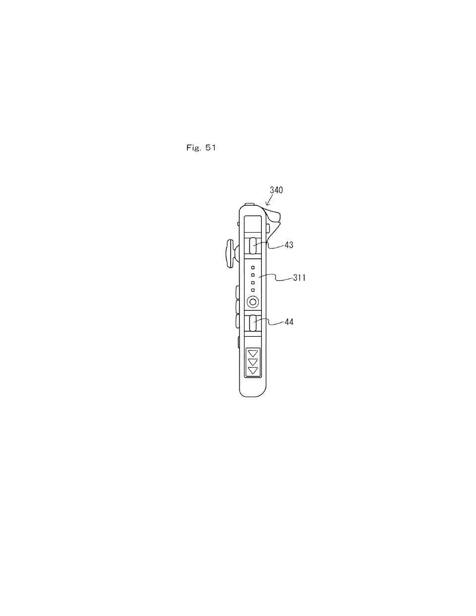
[0809] The controller includes a light-emitting portion (e.g., the indicator LED 45 for the left controller 3) provided on a surface of the slider 311 for notifying a user of predetermined information. Then, predetermined information (e.g., the status of the information processing device 1) can be indicated to the user using the controller.
[0810] Note that the light-emitting portion may indicate the communication status between the main unit 2 and the controller. For example, in the embodiment described above, the indicator LED indicates a number that is assigned to the controller as a result of communication (more specifically, the number represented by the number information described above). For example, the indicator LED may indicate the status of wireless communication between the information processing device 1 and the controller. Specifically, the indicator LED may indicate whether or not wireless communication is available at that point in time or may indicate whether or not pairing has been done.
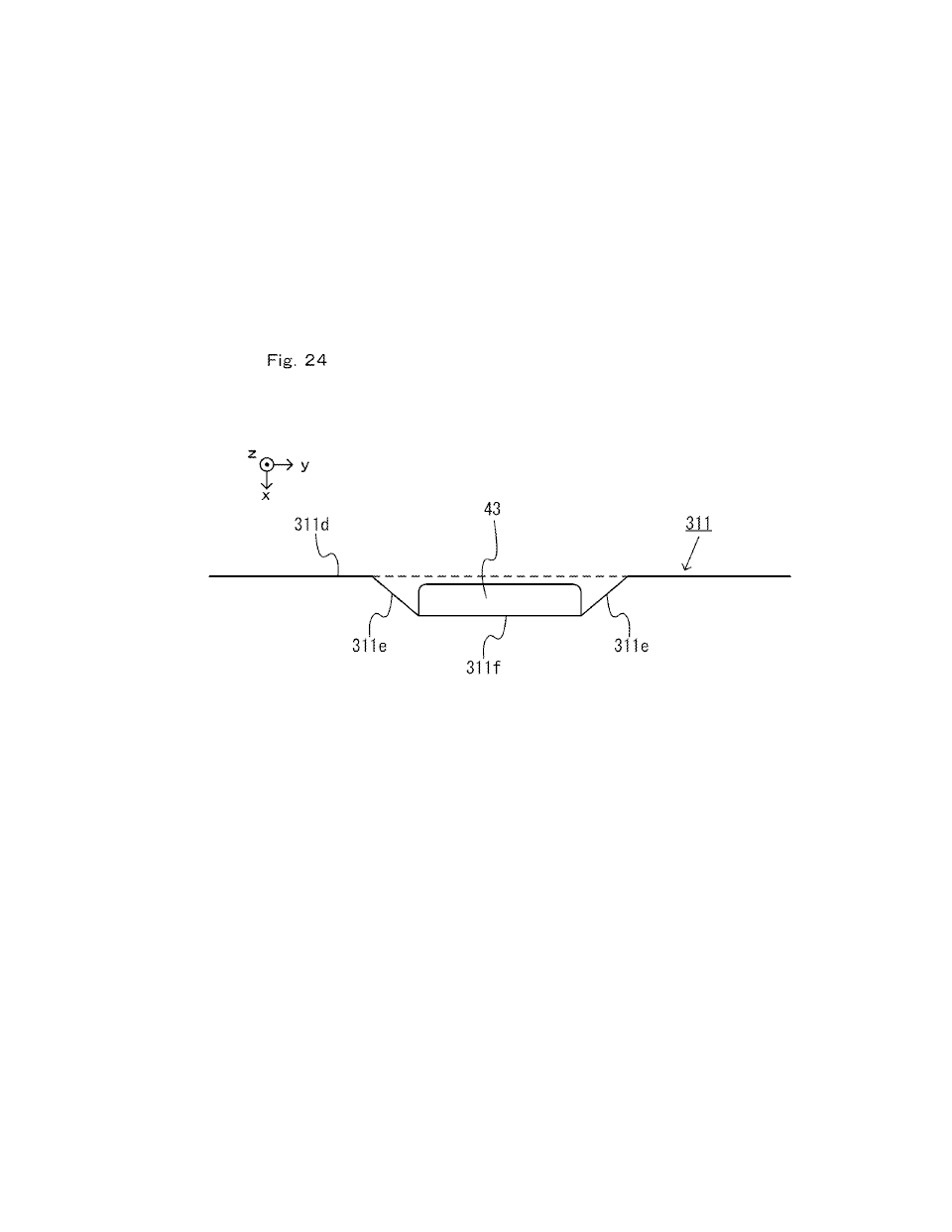
[0811] The controller includes operation sections provided on a surface of the slider 311 (e.g., the second L button 43 and the second R button 44 for the left controller 3). Note that the "operation section" for example means any input section operated by a user, such as buttons, a stick, etc. Thus, more operation sections are available when the controller is removed from the main unit 2 than when the controller is attached to the main unit 2. Therefore, a user is allowed to perform a variety of operations even when the controller is removed from the main unit 2, and it is possible to improve the controllability of the controller.
[0812] Note that in other embodiments, the main unit 2 may include operation sections (e.g., buttons) provided on the engaged surface (i.e., the left side surface or the right side surface of the main unit 2) to which the left controller 3 or the right controller 4 is attached. Note that the operation section may be a button having a particular function, which may specifically be a power button, a home button or a sleep button. For example, in the embodiment described above, the power button 28 may be provided on the left side surface or the right side surface of the main unit 2. Then, the power button 28 cannot be operated when the left controller 3 or the right controller 4 is attached, thereby preventing an erroneous operation by a user. Note that when an operation section is provided on a side surface of the main unit 2, the operation section may be provided on the rail member or on another portion of the housing other than the rail member.
[0813] Note that an operation section having the same function as the operation section described above may be provided on the left controller 3 and/or the right controller 4. For example, in other embodiments, a power button having the same function as the power button 28 may be provided on the left controller 3 and/or the right controller 4. Then, the function of the input section is available to the user even when the left controller 3 and the right controller 4 are in the attached state.
[0814] In other embodiments, the main unit 2 may include a terminal for connecting other devices provided on the engaged surface (i.e., the left side surface or the right side surface of the main unit 2) to which the left controller 3 or the right controller 4 is attached. For example, in the embodiment described above, the first slot 23 and/or the second slot 24 (in other words, terminals provided in the slots) may be provided on the left side surface or the right side surface of the main unit 2. Then, with the controller attached to the main unit 2, the terminals can be protected by the controller. If a slot is provided on the left side surface or the right side surface of the main unit 2, it is possible to prevent a device inserted in the slot (e.g., a card storage medium) from coming off of the main unit 2, when the controller is attached to the main unit 2.
[0815] In the embodiment described above, connecting portions (i.e., the upper left portion and the lower left portion) between the first side surface (i.e., the left side surface) of the four side surfaces of the left controller 3 and side surfaces adjacent thereto (i.e., the upper side surface and the lower side surface) have a more rounded shape than connecting portions (i.e., the upper right portion and the lower right portion) between the second side surface (i.e., the right side surface) opposite from the first side surface and side surfaces adjacent thereto (i.e., the upper side surface and the lower side surface) (see FIG. 5). Moreover, connecting portions between the third side surface (i.e., the right side surface) of the four side surfaces of the right controller 4 and side surfaces adjacent thereto (i.e., the upper side surface and the lower side surface) have a more rounded shape than connecting portions (i.e., the upper side surface and the lower side surface) between the fourth side surface (i.e., the left side surface) opposite from the third side surface and side surfaces adjacent thereto (see FIG. 6). Thus, the controller has a rounded shape on one side thereof, and it is therefore easy for a user to understand the orientation in which to hold the controller removed from the main unit 2. This also makes it easier for a user to hold the controller removed from the main unit 2.
[0816] Moreover, in the embodiment described above, the left controller 3 is attached to the main unit 2 with the second side surface of the left controller 3 facing the fifth side surface (i.e., the left side surface) of the four side surfaces of the main unit 2 (see FIG. 2). Moreover, the right controller 4 is attached to the main unit 2 with the fourth side surface of the right controller 4 facing the sixth side surface (i.e., the right side surface) opposite from the fifth side surface of the main unit 2 (see FIG. 2).
[0817] Then, with the controllers 3 and 4 attached to the main unit 2 (see FIG. 1), the information processing device 1 will have an overall shape such that the left side and the right side thereof are rounded, making it easier for a user to hold. The left side of the left controller 3 is more rounded than the right side thereof, whereas the right side of the right controller 4 is more rounded than the left side thereof (FIG. 5 and FIG. 6). Thus, since the left controller 3 has a different overall shape than that of the right controller 4, it is possible to reduce the possibility that a user mistakes the left and right controllers for each other when attaching them to the main unit 2.
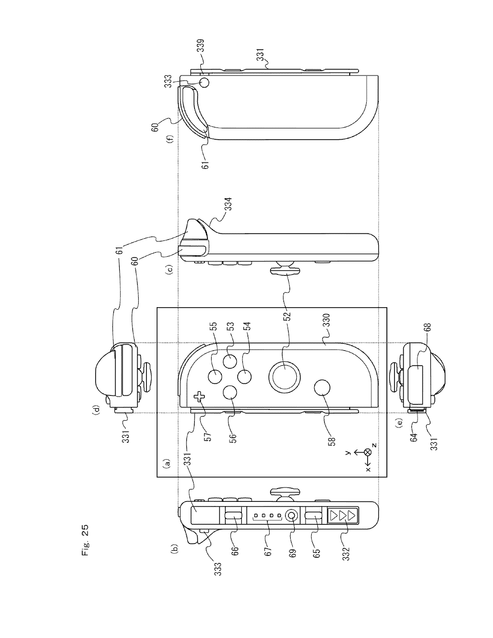
[0818] In the embodiment described above, the right controller 4 includes an input section having a first function that the left controller 3 does not have (in the embodiment described above, the plus button 57, the home button 58 and the infrared image-capturing section 123). In other words, in the embodiment described above, the left controller 3 includes one or more input sections having a predetermined number of types of functions (13 in the embodiment described above, including nine buttons, the analog stick 32, the acceleration sensor 104 and the angular velocity sensor 105). In contrast, the right controller 4 includes one or more input sections having a number (different from the predetermined number) of types of functions (15 in the embodiment described above, including 11 buttons, the analog stick 52, the acceleration sensor 114, the angular velocity sensor 115 and the infrared image-capturing section 123). Thus, when each controller has some functions that the other controller does not have (as compared with a case in which the controllers both have the same functions), it is possible to simplify the configuration of the controllers.
[0819] Note that the "input section having the first function" may be an image-capturing device (e.g., the infrared image-capturing section 123) or a button. The button may be a button having a particular function (e.g., a power button or a home button), for example.
[0820] In the embodiment described above, the left controller 3 includes input sections having the second function different from the first function (e.g., the analog stick 32 and the buttons 33 to 38 in the embodiment described above), and the right controller 4 includes input sections having the second function (e.g., the analog stick 52 and the buttons 53 to 56, 60 and 61 in the embodiment described above). Then, a user can use the second function on either controller, thereby improving the controllability, whereas the first function is omitted for one of the controllers, thereby simplifying the configuration of the controller.
[0821] In the embodiment described above, communication between the main unit 2 and a controller when the controller is attached to the main unit 2 uses a first communication scheme (specifically, wired communication), and communication between the main unit 2 and a controller when the controller is removed from the main unit 2 uses a second communication scheme (specifically, wireless communication) different from the first communication scheme. Then, by changing the communication scheme between when the controller is attached to the main unit 2 and when the controller is removed from the main unit 2, the controller can communicate in either case. The controller can easily communicate with the main unit 2 in wired communication when it is attached to the main unit 2, and the controller can communicate with the main unit 2 in wireless communication when it is removed from the main unit 2.
[0822] In the embodiment described above, the wired communication between the main unit and the controller is a communication connection via a wired communication channel formed by electrically connecting the first terminal of the main unit 2 (specifically, the left-side terminal 17 or the right-side terminal 21) and the second terminal of the controller (specifically, the terminal 42 or 64). The wired communication as used herein means communication via a cable connection between devices, and also means communication via a connection between a terminal (e.g., a connector) of one device and a terminal (e.g., a connector) of the other device.
[0823] In the embodiment described above, when the controller is attached to the main unit 2, the first terminal of the main unit 2 (i.e., the left-side terminal 17 or the right-side terminal 21) and the second terminal of the controller (i.e., the terminal 42 or 64) are electrically connected to each other by being in contact with each other. Then, when the controller is attached to the main unit 2, wired communication and/or power supply are implemented via the terminals connected together.
[0824] In the embodiment described above, when the controller is attached to the main unit 2, the first terminal of the main unit 2 and the second terminal of the controller are electrically connected together, and the communication between the main unit 2 and the controller and the power supply from the main unit 2 to the controller are implemented via the first terminal and the second terminal. Then, it is possible to increase the opportunity to charge the controller and thus to reduce the possibility of the controller running out of battery. When a user attaches controllers to the main unit 2 so as to use the information processing device 1 as an integral portable device, the controllers can be charged without the user knowing. Therefore, the user does not need to perform a separate operation for charging the controller, thus saving the trouble for the user.
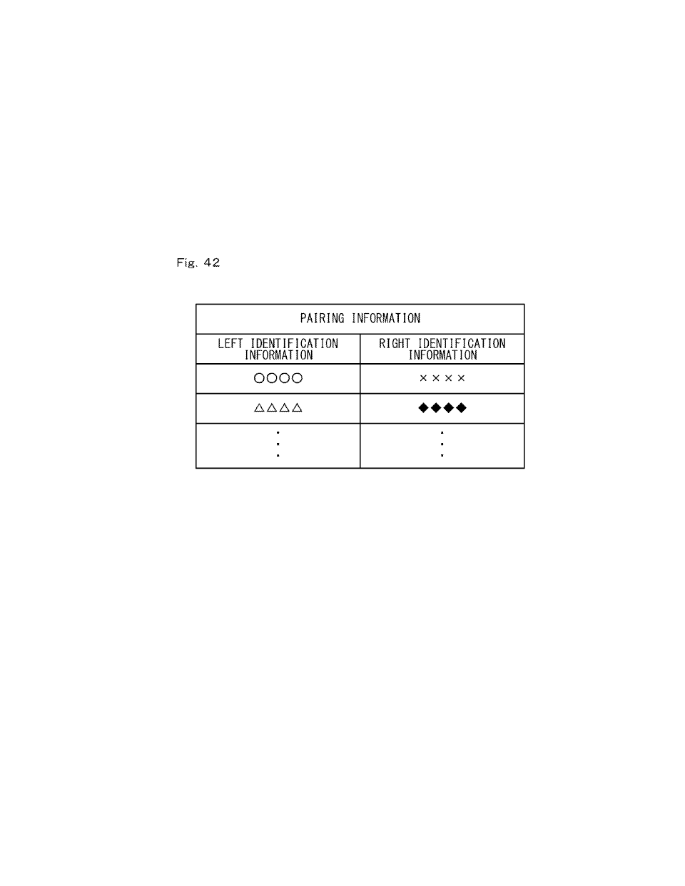
[0825] In the embodiment described above, the information processing device 1 includes a first sensing section (e.g., the CPU 81 executing step S3) for sensing the attachment of the left controller 3 to the main unit 2, and a second sensing section (e.g., the CPU 81 executing step S3) for sensing the attachment of the right controller 4 to the main unit 2. The main unit 2 registers a pair of a left controller and a right controller based on the sensing results from the first sensing section and the second sensing section (see step S4). Therefore, a user can register a pair through a straightforward, easy operation of attaching two controllers, to be used as a pair, to the main unit 2.
[0826] In the embodiment described above, when the left controller 3 and the right controller 4 are attached to the main unit 2, the main unit 2 registers the left controller 3 and the right controller 4 attached thereto as a pair (see step S3, S4). Thus, a user can register a pair of controllers through a straightforward operation.
[0827] Note that the first sensing section and the second sensing section may or may not simultaneously sense the attachment of the controllers to the main unit 2. That is, two controllers that are not at the same time attached to the main unit 2 may be registered as a pair.
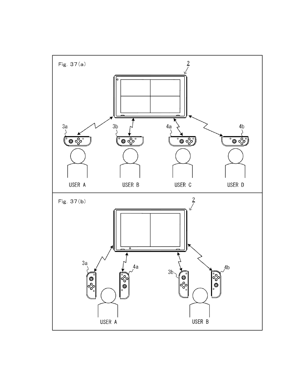
[0828] The main unit 2 may execute a predetermined information process based on operation data received from two pairs of controllers. For example, the main unit 2 receives operation data from each of a left controller and a right controller that are registered as a first pair, and receives operation data from each of a left controller and a right controller that are registered as a second pair. The main unit 2 may execute a predetermined information process using, as a set of data, operation data received from controllers that are registered as a first pair, and using, as another set of data, operation data received from controllers that are registered as a second pair. Then, the information processing device can use operation data from a plurality of controllers while distinguishing between operation data from different registered pairs.
[0829] In the embodiment described above, when receiving operation data from each of the left controller 3 and the right controller 4 that are removed from the main unit 2 and registered as a pair, the main unit 2 executes a predetermined information process using the two pieces of operation data received as a set of data (see FIG. 37(b)). Thus, a user can perform operations using controllers registered as a pair. For example, a user can control one object by using a pair of controllers.
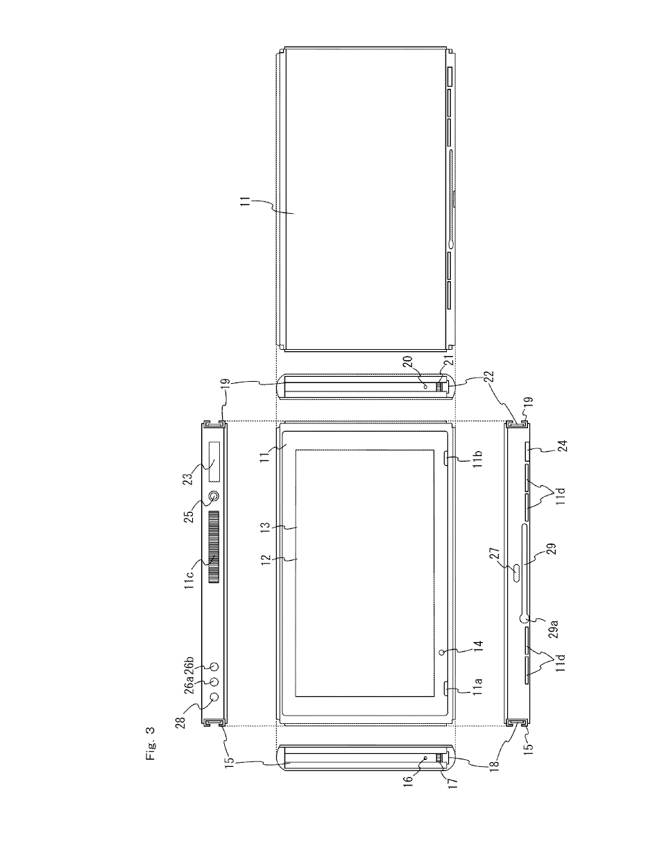
[0830] In the embodiment described above, the main unit 2 includes the housing 11 provided with a first engagement portion (which can also be referred to as the attachment and detachment mechanism; specifically, the left rail member 15) to be engaged with the housing (specifically, the slider 40 provided on the housing 31) of the left controller 3, and a second engagement portion (specifically, the right rail member 19) to be engaged with the housing (specifically, the slider 62 provided on the housing 51) of the right controller 4.
[0831] In the above description, the first engagement portion and the second engagement portion are to be engaged with controller housings (including members provided on the housings), and are not to be engaged with connectors of the controllers. That is, in the present embodiment, the main unit 2 is configured so that controllers can be attached to and detached from the main unit 2 by the method of engaging the engagement portions with the controllers, which is different from the method of connecting the connectors of the main unit 2 with those of the controllers (the engagement method and the method of connecting the connectors may be both used at the same time). Then, the main unit 2 and the controllers can be firmly connected together.
[0832] Note that in other embodiments, the main unit 2 may include only one engagement portion to be engaged with the housing of the controller or may include three or more engagement portions.
[0833] In the embodiment described above, the left controller 3 includes the housing 31 provided with a third engagement portion (specifically, the slider 40) to be engaged with the first engagement portion of the main unit 2. The right controller 4 includes the housing 51 provided with a fourth engagement portion (specifically, the slider 62) to be engaged with the second engagement portion of the main unit 2. Thus, members are provided also on the controller side, which members are to be engaged with the engagement portions on the main unit 2 side are provided, and it is therefore possible to more firmly connect the main unit 2 and the controllers together.
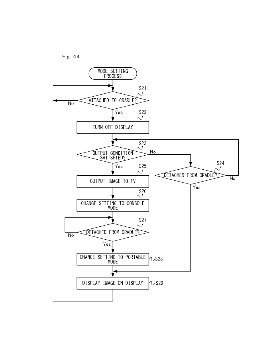
[0834] In the embodiment described above, the main unit 2 selectively outputs the execution result of the information process to either the display (the display 12) or a display device (the TV 6) separate from the main unit 2 (see FIG. 44). This enables two different modes of use, including a mode in which images are displayed on the display of the main unit 2, and another mode in which images are displayed on a display device separate from the main unit 2.
[0835] In the embodiment described above, the engagement portion of the main unit 2 is a rail member (referred to also as the first slide member) provided on a surface of the housing 11 of the main unit 2. The controller includes a slider (referred to also as the second slide member) which slidably and detachably engages with the rail member. In the embodiment described above, the rail member and the slider together form a slide mechanism (see FIG. 7). Thus, the slide mechanism allows for firm locking between the main unit 2 and the controllers and allows for easy attachment and detachment of the controllers.
[0836] In the embodiment described above, the rail member is formed so that the slider can slidably engage with the rail member in a predetermined direction (specifically, the y-axis direction shown in FIG. 1), and so that the slider can be inserted and detached into and from the rail member via one end thereof in the predetermined direction (see FIG. 2). Thus, it is possible to easily attach and detach controllers to and from the main unit 2 via the end.
[0837] Moreover, in the embodiment described above, the rail member is provided so as to extend in the up-down direction of the main unit 2 so that the slider can be inserted and detached into and from the rail member via the upper end thereof (see FIG. 2). Thus, controllers can be conveniently attached and detached to and from the main unit 2 while the main unit 2 is placed upright. For example, in the present embodiment, controllers can be attached and detached to and from the main unit 2 while the main unit 2 is attached to the cradle 5.
[0838] In the embodiment described above, the slide member of the main unit 2 is provided so as to extend generally over the entirety (e.g., so that the length of the slide member is at least one 80% or more of the length of the housing 11 of the main unit 2) of a surface of the housing 11 of the main unit 2 in a predetermined direction (specifically, the up-down direction) (see FIG. 3). Thus, when a controller is attached to the main unit 2, the controller is connected generally over the entirety of the aforementioned surface of the main unit 2, thereby allowing the controller to be firmly connected to the main unit 2.
[0839] In the embodiment described above, the first slide member of the main unit 2 (i.e., the rail member) has a C-shaped cross section, and the second slide member of the controller (i.e., the slider) has a T-shaped cross section. Note that in other embodiments, the first slide member of the main unit 2 may have a T-shaped cross section, and the second slide member of the controller may have a C-shaped cross section.
[0840] In the embodiment described above, the controller includes a terminal (e.g., the terminal 42 or 64) for communication with the main unit 2. The main unit 2 includes a terminal (i.e., the left-side terminal 17 or the right-side terminal 21) provided on the housing 11 at such a location that allows the terminal to be connected to a terminal of a controller when the controller is attached to the main unit 2. Thus, when the controller is attached to the main unit 2, the terminals are connected together, enabling wired communication.
[0841] In the embodiment described above, the information processing device 1 can be said to be a game system capable of executing game applications. When at least the left controller 3 and the right controller 4 are removed from the main unit 2 (in other words, when the two controllers are both removed from the main unit 2), the left controller 3 and the right controller 4 each transmit operation data representing operations performed on the left controller 3 and the right controller 4 to the main unit 2 via wireless communication. Thus, in the embodiment described above, it is possible to provide a novel game system that can be used with two controllers removed.
[0842] In the embodiment described above, the information processing device 1 can be said to be a hand-held information processing device including a main section (i.e., the main unit 2) having a display (i.e., the display 12), a first controller section (i.e., the left controller 3) and a second controller section (i.e., the right controller 4) for performing a predetermined information process in response to an operation performed on either the first controller section or the second controller section. When the first controller section and the second controller section are removed from the main section, the main unit 2 performs a predetermined information process based on operation data representing an operation performed on either the first controller section or the second controller section, and displays the results of the information process on the display. Thus, in the embodiment described above, it is possible to provide a novel information processing device that can be used in a mode in which two controller sections are removed.
[0843] In the above description, the first controller section and the second controller section are arranged so that when the first controller section is attached to the main section, a user (i.e., the user holding the information processing device) can operate the first controller section with one hand and operate the second controller section with the other hand (see FIG. 33). Thus, it is possible to provide a novel information processing device that can be used both in a mode in which the controller sections are attached to the main section and in a mode in which the controller sections are removed from the main section.
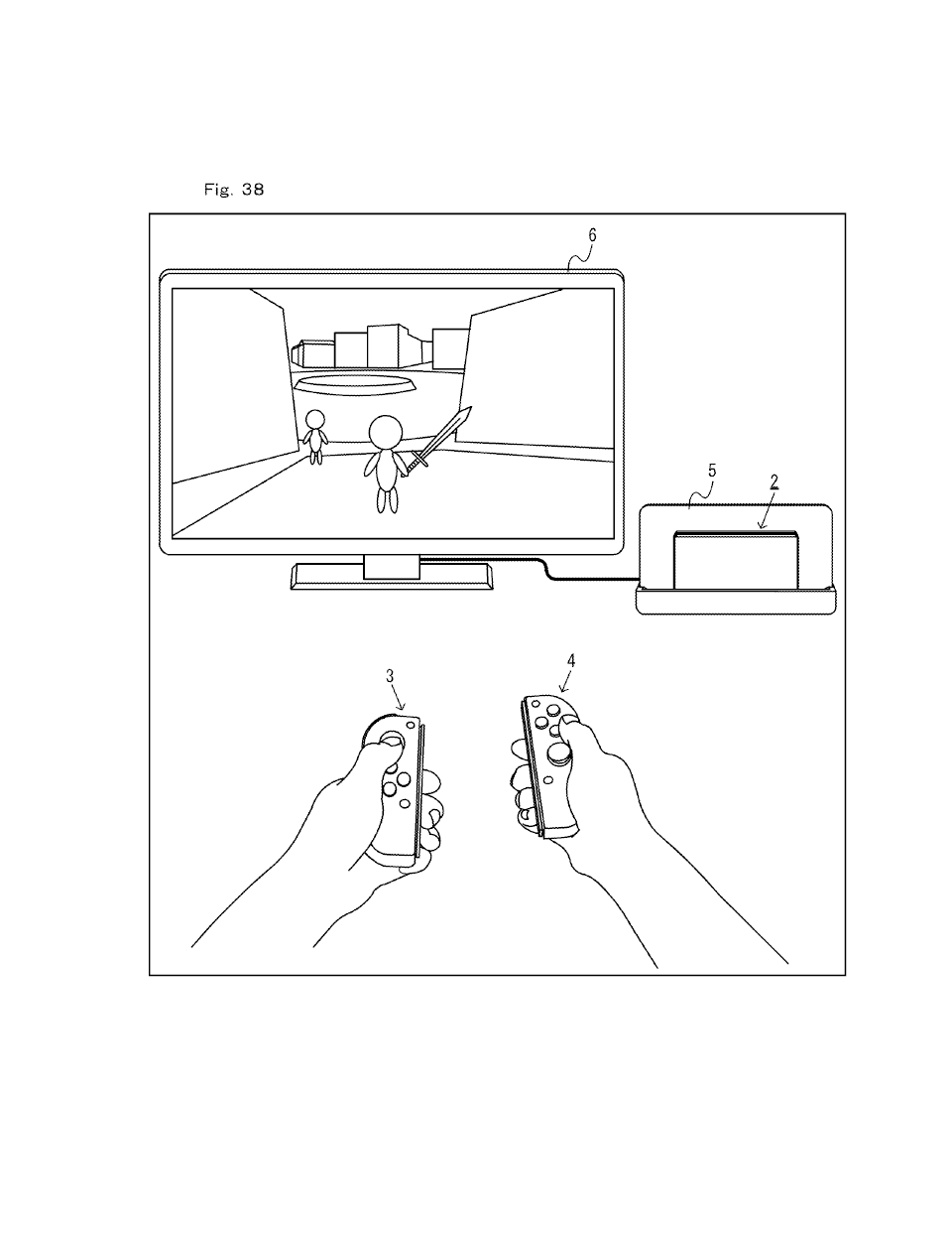
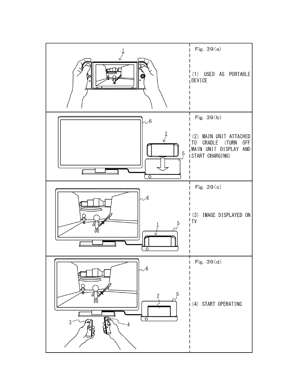
[0844] The information processing system of the present embodiment includes the main unit 2, and controllers (specifically, the left controller 3 and the right controller 4; referred to also as controller devices) that can be attached to and detached from the main unit 2. The main unit 2 includes the display 12 (referred to also as the display). When controllers are attached to the main unit 2, the main unit 2 can display, on the display 12, images that are obtained based on operations performed on the controllers. When the controllers are removed from the main unit 2, the main unit 2 can display, on an external display device (specifically, the TV 6) separate from the main unit 2, images that are obtained based on operations performed on the controllers. Note that in the above description, there may be one controller that can be attached to the main unit or there may be a plurality of controllers that can be attached to the main unit.
[0845] As described above, the information processing device 1 can be used both in a mode in which controllers are attached to the main unit 2 and in a mode in which the controllers are removed from the main unit. Thus, since a plurality of modes of use are realized with a single information processing device 1, the information processing device 1 can be used in a wider variety of manners. As described above, when the controllers are removed from the main unit 2, an external display device can be used as the display device. Thus, a user can provide, as the external display device, a display device having a larger screen size than the display 12, so that it is possible to display the images on a larger screen.
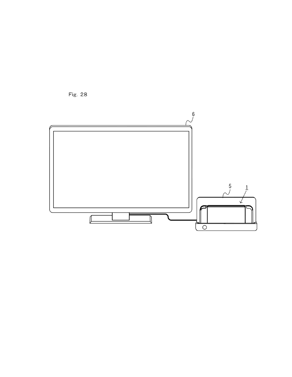
[0846] In the embodiment described above, the information processing system can communicate with the TV 6, and further includes the cradle 5 (referred to also as an add-on device) to and from which the main unit 2 can be attached and detached. The main unit 2 detects the attachment of the main unit 2 to the cradle 5, and determines whether the images obtained based on operations performed on the controllers is displayed on the display 12 or displayed on the TV 6 based at least on the detection results (step S21, S25, S29). Thus, the main unit 2 can determine the image display output based on whether or not the main unit 2 is attached to the cradle 5.
[0847] Note that in the above description, there is no particular limitation on the method for determining the image display output. As in the embodiment described above, the main unit 2 may select the TV 6 as the image display output at least on the condition that the main unit 2 is attached to the cradle 5. In other embodiments, the main unit 2 may select the TV 6 as the image display output when the main unit 2 is attached to the cradle 5. That is, the main unit 2 may output the images to the TV 6 via the cradle 5 in response to the attachment of the main unit 2 to the cradle 5.
[0848] In other embodiments, the main unit 2 may be capable of communicating directly with the TV 6. For example, the main unit 2 and the TV 6 may be capable of communicating with each other in wireless communication. Also in such a case, as in the embodiment described above, the main unit 2 may determine the image display output based on the attached state of the main unit 2 to the cradle 5.
[0849] The add-on device (e.g., the cradle) may be any add-on device to and from which the main unit 2 can be attached and detached. The add-on device may or may not have the function of charging the main unit 2, as in the present embodiment.
[0850] In the embodiment described above, the cradle 5 is enabled to communicate with the main unit 2 at least on the condition that the main unit 2 is attached thereto. If the main unit 2 has determined to display the images based on operations performed on the controllers on the TV 6, the main unit 2 outputs the images to the TV 6 via the cradle 5. Thus, the main unit 2 can display the images on the TV 6 by outputting the images to the TV 6 via the cradle 5. Therefore, the main unit 2 does not need to communicate with the TV 6, thereby simplifying the configuration of the main unit 2.
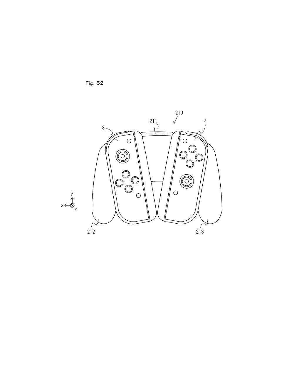
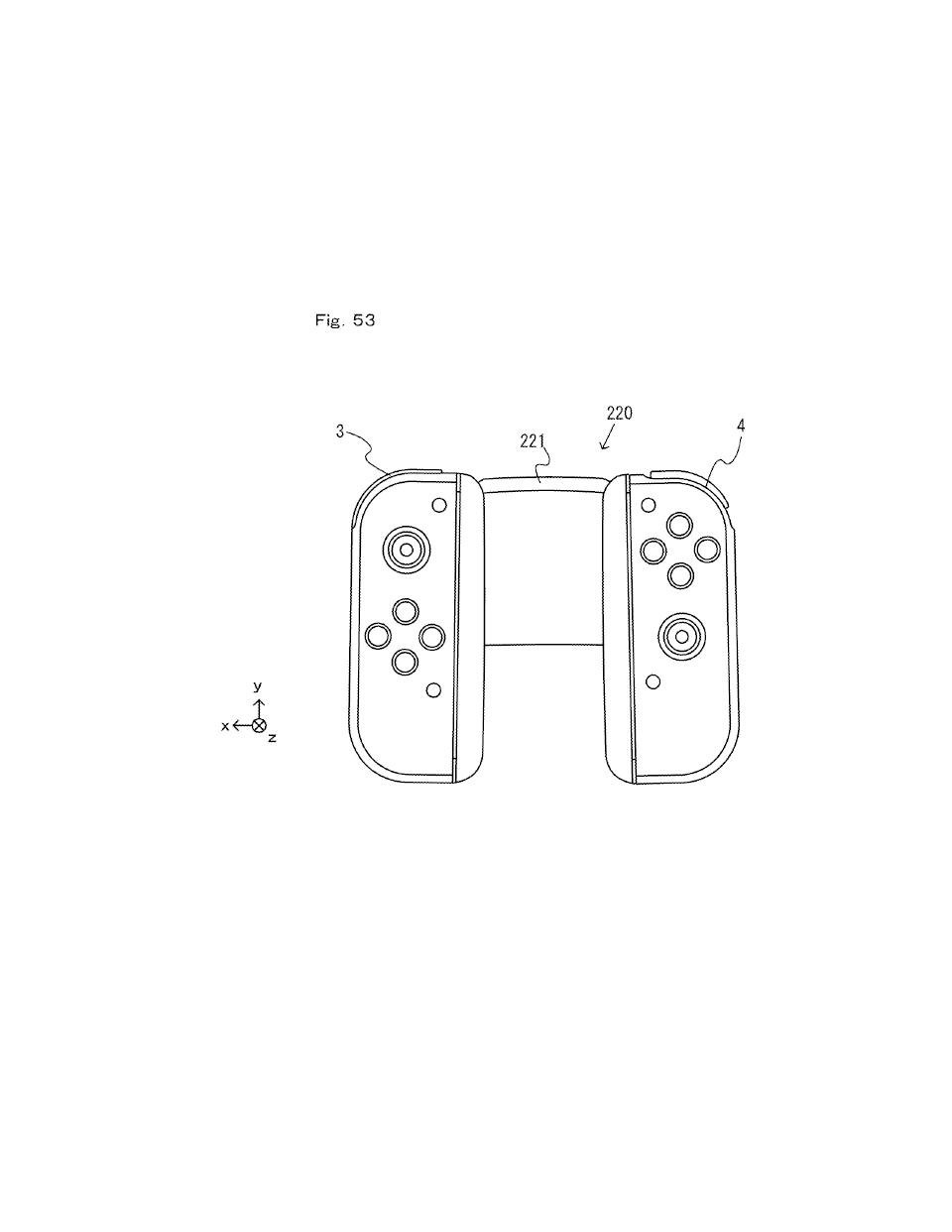
[0851] The information processing system of the embodiment described above includes the main unit 2, the left controller 3 (referred to also as the first controller device), the right controller 4 (referred to also as the second controller device), and an accessory (e.g., the extension grip 210 or the attachment 220). The left controller 3 can be attached to and detached from the main unit 2 or the accessory. The right controller 4 can be attached to and detached from the main unit 2 or the accessory. The main unit 2 includes the display 12 (referred to also as the display), and displays, on the display 12, the execution result of a predetermined information process based on operations performed on the left controller 3 and the right controller 4. The left controller 3 and the right controller 4 can be attached to the accessory at the same time (see FIG. 52). Thus, by using the accessory, a user can hold the two controllers 3 and 4, removed from the main unit 2, as an integral unit. That is, it is possible to improve the controllability of the controllers when removed from the main unit 2.
[0852] In the embodiment described above, the left controller 3 is attached to the accessory on the left side of the center of the accessory, and the right controller 4 is attached to the accessory on the right side of the center of the accessory (see FIG. 52, FIG. 53). Thus, a user can operate the left controller 3 attached to the accessory with the left hand, and operate the right controller 4 attached to the accessory with the right hand. That is, a user can operate the controllers in a similar fashion to that when the controllers are not attached to the accessory, thereby providing an accessory having a good controllability.
[0853] In the embodiment described above, the accessory includes a first grip portion (i.e., the left grip portion 212) provided on the left side and a second grip portion (i.e., the right grip portion 213) provided on the right side. Then, a user can operate the controllers while holding the grip portions respectively with the left hand and the right hand, thereby providing an accessory having a good controllability.
[0854] In the embodiment described above, the first grip portion is provided on the left side of the area where the left controller 3 is attached. The second grip portion is provided on the right side of the area where the right controller 4 is attached (see FIG. 52). Therefore, by holding the grip portions, a user can easily operate the controllers 3 and 4 attached to the accessory.
[0855] (Functions/Effects Regarding Controller Terminals, Etc.)
[0856] In the embodiment described above, a game controller (e.g., the left controller 3 or the right controller 4) is removably attachable to a main unit (e.g., the main unit 2) having a main unit-side slide member (e.g., the left rail member 300) and configured to execute a game process.
[0857] The game controller includes: [0858] an operation section (e.g., the analog stick 32, 52, the operation buttons 33 to 39, 43, 44, 46, 47, 53 to 61, 65, 66, 69); and [0859] a controller-side slide member (e.g., the slider 311, 331) protruding from a first surface of the game controller and configured to slidably engage with the main unit-side slide member in a slide direction (e.g., the up-down direction shown in FIG. 14, i.e., the y-axis direction).
[0860] The controller-side slide member has a first end and a second end in the slide direction, and the game controller is configured to be attached to the main unit by inserting the controller-side slide member into the main unit-side slide member from the first end (e.g., the lower end of the slider 331 shown in FIG. 14, i.e., the end on the y-axis negative direction side).
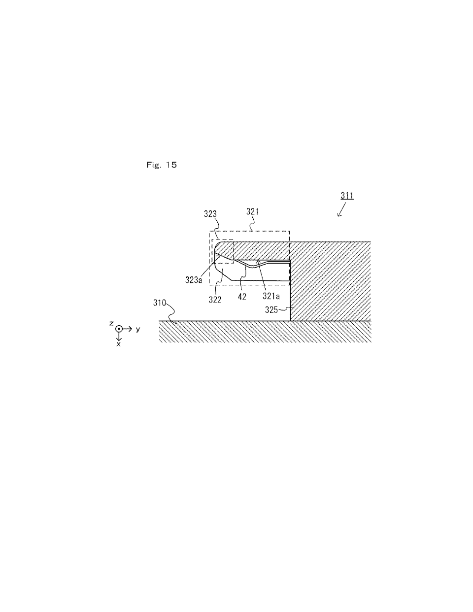
[0861] The controller-side slide member includes: [0862] a protruding portion (e.g., the protruding portion 321) protruding from the first end side of the controller-side slide member in the slide direction and having a facing surface (e.g., the facing surface 321a) that faces the first surface (e.g., the right side surface of the left controller 3 or the left side surface of the right controller 4) of the game controller; and [0863] at least one terminal (e.g., the terminal 42, 64) between the facing surface and the first surface, wherein the terminal is configured to be electrically connected to the main unit.
[0864] Thus, the game controller can be easily attached to the main unit by means of the slide mechanism, and it is therefore possible to provide a game controller having a high usability. Then, a user can also connect terminals together through the operation of inserting and sliding the controller-side slide member against the main unit-side slide member. Therefore, a user can easily perform the attachment operation, which includes the operation of connecting terminals together. With the provision of the protruding portion on the controller-side slide member, it is possible to reduce the possibility that the terminals come into contact with a hand of a user or other objects, thereby always protecting the terminals.
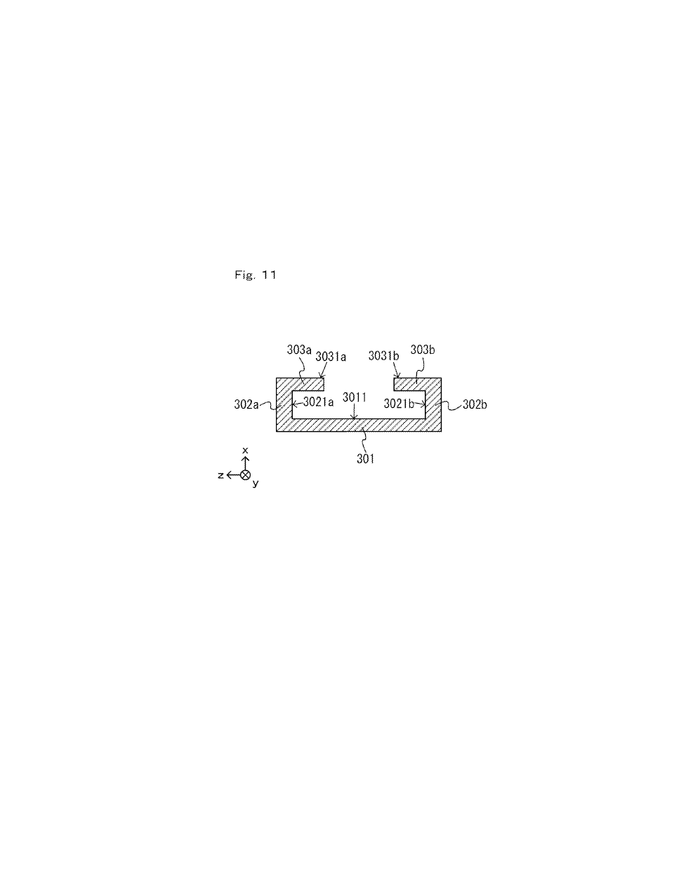
[0865] The term "slide member" may refer to the rail member or the slider as used in the embodiment described above. Note that in the embodiment described above, a slide member provided on the main unit 2 side and a slide member provided on the controller side are referred to as a "rail member" and a "slider", respectively, so that these members can easily be distinguished from each other. The shape of the rail member and that of the slider are not limited to those of the embodiment described above. For example, a slide member having a cross section shaped as shown in FIG. 11 may be referred to as a "slider", and a slide member having a T-shaped cross section as shown in FIG. 22 may be referred to as a "rail member".
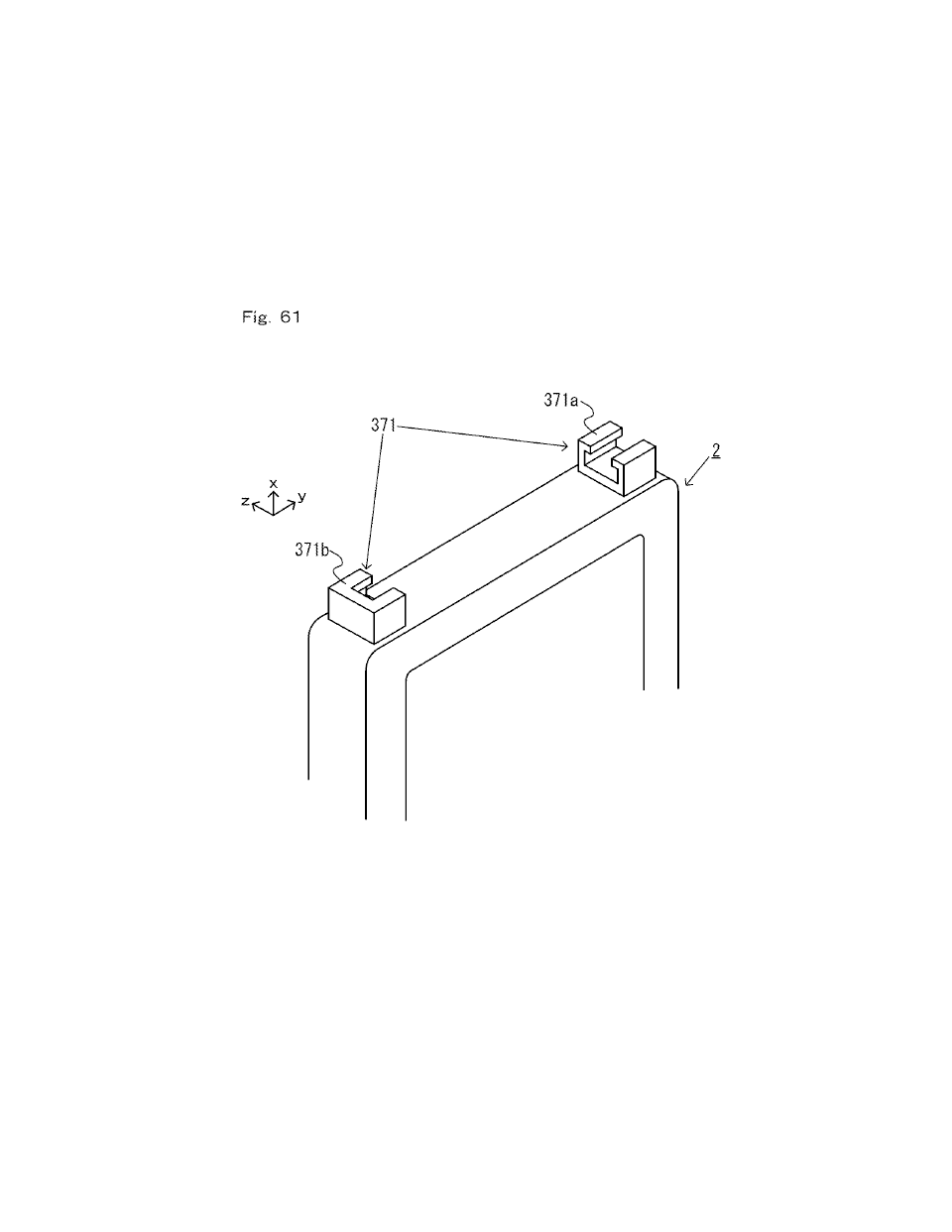
[0866] Moreover, a slide member is not limited to those that have a shape elongated in the slide direction, as does the rail member or the slider of the embodiment described above. FIG. 61 is a diagram showing another example slide member provided on the main unit. The main unit 2 may include a slide member 371 shown in FIG. 61, instead of the rail member of the embodiment described above.
[0867] As shown in FIG. 61, the slide member 371 includes an upper slide member 371a provided on an upper portion of the left side surface of the main unit 2, and a lower slide member 371b provided on a lower portion of the left side surface of the main unit 2. Each of the slide members 371a and 371b includes a bottom surface portion, a side surface portion and a top surface portion, as does the left rail member 300 described above. Therefore, each of the slide members 371a and 371b slidably engages with the slider 311 as the slider 311 of the left controller 3 is inserted into the groove formed by the bottom surface portion and the side surface portion. With the slider 311 inserted in the groove of the slide members 371a and 371b, the slider 311 is securely locked by the top surface portion so as not to come off in the direction perpendicular to the slide direction. The lower slide member 371b includes a facing portion similar to that of the left rail member 300 described above. Therefore, when the slider 311 is inserted into the groove of the slide members 371a and 371b, the slider 311 can be slid to a position at which the slider 311 is in contact with the facing portion, and the slide movement is limited to this position. Thus, the slide member 371 shown in FIG. 61 can also slidably engage with the slider 311 of the left controller 3, as does the left rail member 300.
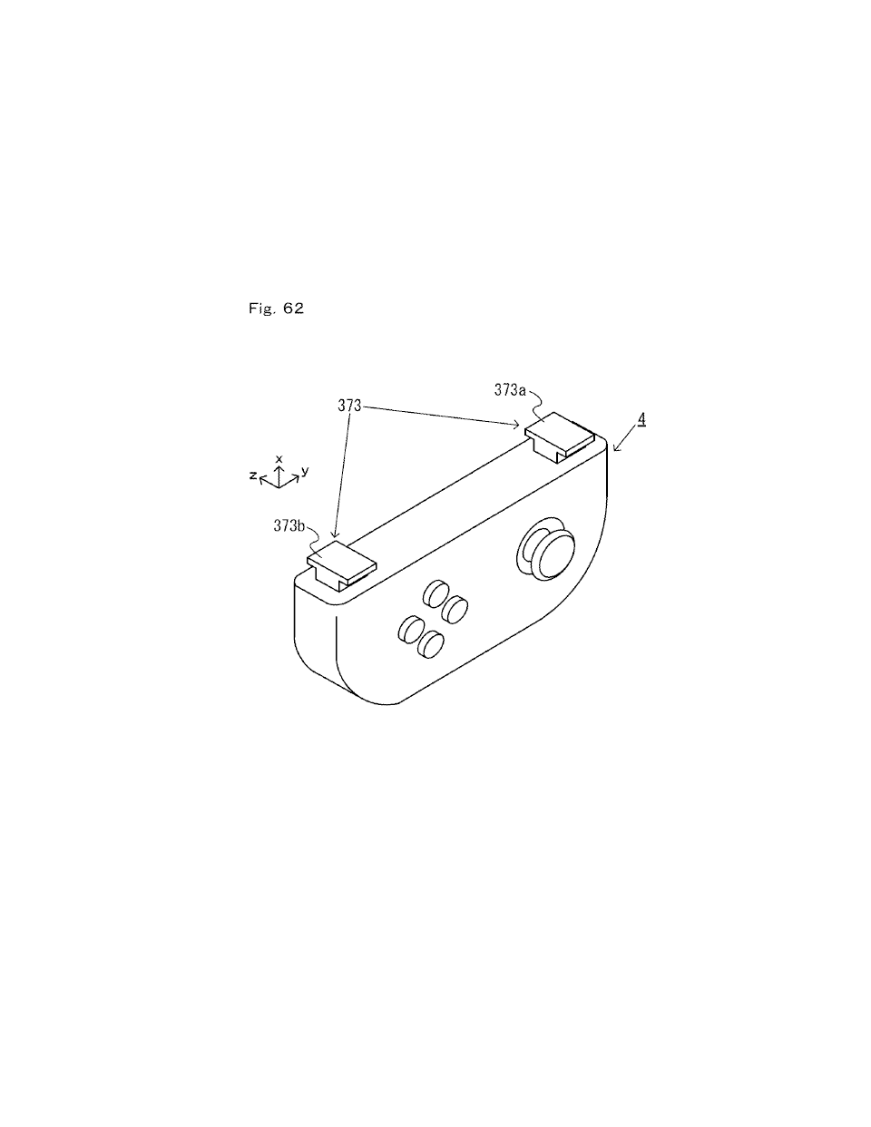
[0868] FIG. 62 is a diagram showing another example slide member provided on the right controller 4. The right controller 4 may include a slide member 373 shown in FIG. 62, instead of the slider 331 of the embodiment described above.
[0869] As shown in FIG. 62, the slide member 373 includes an upper slide member 373a provided on an upper portion of the left side surface of the right controller 4, and a lower slide member 373b provided on a lower portion of the left side surface of the right controller 4. Each of the slide members 373a and 373b includes a shaft and a top surface portion similar to those of the slider 331 described above. Therefore, the slide members 373a and 373b slidably engage with the left rail member 300 by being inserted into the left rail member 300 of the main unit 2. With the slide members 373a and 373b inserted in the groove of the left rail member 300, the slide members 373a and 373b is securely locked by the top surface portion so as not to come off in the direction perpendicular to the slide direction. Thus, the slide member 373 shown in FIG. 62 can also slidably engage with the left rail member 300 of the main unit 2, as does the slider 331.
[0870] As described above, a slide member does not need to be formed by a single member extending in the slide direction, but may be formed by a plurality of members arranged with each other in the slide direction. Note that when a slide member is formed by a plurality of members, the upper end of the slide member refers to the upper end of one of the plurality of members that is located uppermost, and the lower end of the slide member refers to the lower end of another one of the plurality of members that is located lowermost. In this case, the center of a slide member in a predetermined direction refers to the central position therebetween the opposite ends in the predetermined direction of the slide member including a plurality of members. For example, the center of the slide member in the up-down direction refers to the central position between the upper end position of the uppermost one of the plurality of members and the lower end position of the lowermost one of the plurality of members.
[0871] A slide member may be formed as an integral unit with the housing of a device (e.g., the main unit 2 or the controller) on which the slide member is provided. For example, although the bottom surface of the slide member is separate from the housing of the device on which the slide member is provided in the embodiment described above, the housing of the device on which the slide member is provided may be the bottom surface of the slide member in other embodiments. For example, for the main unit 2, the side surface portion 302 of the rail member described above may be provided directly on the side surface of the housing 11 of the main unit 2. Moreover, the side surface portion may be formed as an integral unit with the housing 11. In other embodiments, the side surface of the housing and the bottom surface portion of the rail member may together form the bottom surface of the slide member. For example, with the extension grip 350 (FIG. 54) of the embodiment described above, the bottom surface of the slide member is formed by the bottom surface portion of the left rail member 356 and the housing (of the support section 352) exposed through the hole 356a formed in the bottom surface portion together (see FIG. 55).
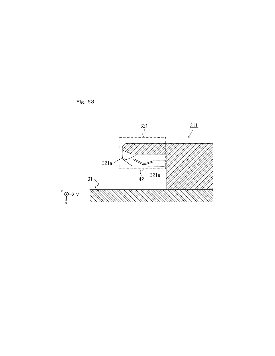
[0872] The terminal may be provided so that at least a portion thereof lies between the facing surface and the first surface, and it is not limited to the embodiment in which it is provided on the facing surface as in the embodiment described above. FIG. 63 is a diagram showing an example terminal arrangement in other embodiments. In other embodiments, the terminal 42 may be arranged as shown in FIG. 63, instead of the arrangement of the terminal 42 shown in FIG. 15. In FIG. 63, the terminal 42 is provided at a position away from the facing surface in the left-right direction (i.e., the x-axis direction). In FIG. 63, a surface of the terminal 42 that is facing toward the first surface is in contact with the left-side terminal 17 (as in the embodiment described above). The position of the left-side terminal 17 of the main unit 2 is adjusted in accordance with the arrangement of the terminal 42 shown in FIG. 63. That is, since the terminal 42 in FIG. 63 is shifted in the x-axis negative direction as compared with the terminal 42 shown in FIG. 15, the left-side terminal 17 of the main unit 2 is accordingly shifted in the x-axis negative direction from the position shown in FIG. 12. Note that in other embodiments, a surface of the terminal 42 that is facing toward the facing surface 321a may be in contact with the left-side terminal 17. In FIG. 63, the facing surface 321a may or may not include the slots 321b.
[0873] As in the embodiment described above and the example shown in FIG. 63, the terminal may be provided so that at least a portion of a surface (of the terminal) that is facing toward the first surface of the controller lies between the facing surface and the first surface (in this case, the surface of the terminal facing toward the facing surface may be arranged between the facing surface and the first surface or may be arranged on the inner side of the protruding portion). Then, with the provision of the protruding portion, it is possible to reduce the possibility that a surface of the terminal to be in contact with another terminal comes into contact with a hand of a user or other objects, thereby efficiently protecting the terminal.
[0874] In the embodiment described above, the terminal extends along the facing surface. Then, since the terminal is arranged closer to the facing surface, it is possible to more efficiently protect the terminal.
[0875] In the embodiment described above, the terminal is on the facing surface. Then, since the terminal is arranged closer to the opposing surface, it is possible to more efficiently protect the terminal.
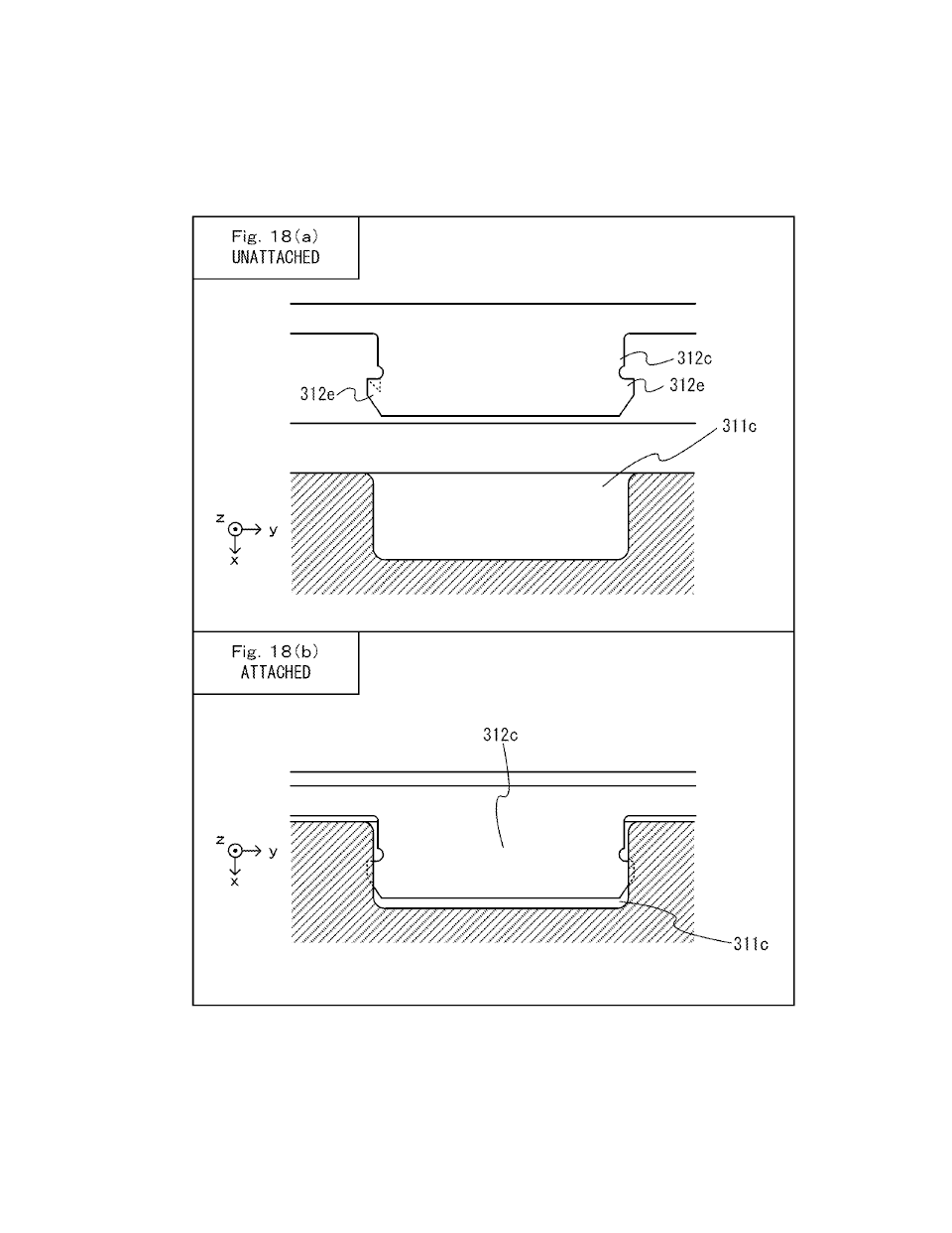
[0876] In the embodiment described above, the terminal is configured to flex into a slot in the facing surface. Then, it is possible to reduce the force to act upon a terminal when the terminal comes into contact with another terminal.
[0877] In the embodiment described above, a side of the terminal that faces the first surface is exposed. Then, the terminal can come into contact with another terminal (e.g., the left-side terminal 17 of the main unit 2 or the right-side terminal 21), using a surface of the terminal that faces the first surface.
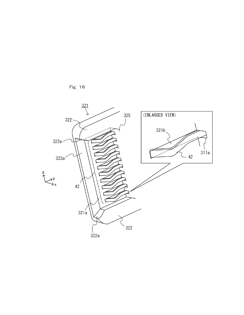
[0878] In the embodiment described above, the protruding portion includes a wall (e.g., the wall portion 322) on the facing surface that protrudes from the facing surface, the wall being on one side or on both sides of the terminal with respect to a direction substantially perpendicular to the slide direction (e.g., the z-axis direction shown in FIG. 15). Then, it is possible with the wall to reduce the possibility that the terminal comes into contact with a hand of a user or other objects, thereby more reliably protecting the terminal.
[0879] In the embodiment described above, an inner wall of the wall facing the terminal flares away from the terminal in a direction that is toward a distal end of the protruding portion (FIG. 16). Then, the inner wall provides alignment between the main unit and the game controller, making it easier for the terminal of the main unit and the terminal of the game controller to properly come into contact with each other.
[0880] In the embodiment described above, a distal end of the terminal is between a center of the controller-side slide member and a distal end (e.g., the distal end of the distal end portion 323 shown in FIG. 15) of the protruding portion (FIG. 15, FIG. 16). Then, since there is a gap between the distal end of the protruding portion and the distal end of the terminal, it is possible to further reduce the possibility that the terminal comes into contact with a hand of a user or other objects, thereby more reliably protecting the terminal.
[0881] In the embodiment described above, the protruding portion is tapered toward the distal end (FIG. 15). Then, the end portion provides alignment between the main unit and the game controller, making it easier for the terminal of the main unit and the terminal of the game controller to properly come into contact with each other.
[0882] In the embodiment described above, an end portion of the protruding portion has a second surface (e.g., the slope 323a shown in FIG. 15) that is sloped away from the first surface toward the distal end of the protruding portion. Then, the end portion provides alignment between the main unit and the game controller, making it easier for the terminal of the main unit and the terminal of the game controller to properly come into contact with each other.
[0883] In the embodiment described above, an intersection between the facing surface and a second surface at the distal end may be a chamfer. Then, the intersection provides smooth alignment between the main unit and the game controller.
[0884] In the embodiment described above, the terminal is one of a plurality (e.g., ten) of terminals between the facing surface and the first surface. The plurality of terminals are arranged next to each other in a direction that is substantially parallel to the facing surface and substantially perpendicular to the slide direction (e.g., the z-axis direction shown in FIG. 16), the terminals being exposed on one side (e.g., the y-axis negative direction side shown in FIG. 16) that corresponds to the first end side of the controller-side slide member. This makes it easier for the terminals of the game controller to come into contact with the terminals of the main unit which come from the first end side.
[0885] The operation section is on a front surface (e.g., the surface on the z-axis negative direction side shown in FIG. 14) of the game controller. The first surface is a side surface (e.g., the right side surface of the left controller 3 or the left side surface of the right controller 4) relative to the front surface. Then, with the game controller attached to the main unit, a user can easily operate the operation section provided on the front surface of the game controller.
[0886] In the embodiment described above, the controller-side slide member is a rail extending substantially parallel to the slide direction (e.g., the slider 311 shown in FIG. 14 or the slider 331 shown in FIG. 25). Then, the game controller can be easily attached to the main unit by inserting the rail into the main unit-side slide member.
[0887] In the embodiment described above, the rail extends from near a first end (e.g., the upper end of the left controller 3 shown in FIG. 14) to near a second end (e.g., the lower end of the left controller 3 shown in FIG. 14) of the first surface in the slide direction. Then, the game controller can be connected firmly to the main unit, and it is possible to reduce the possibility that the game controller comes off the main unit.
[0888] In the embodiment described above, a cross section of the controller-side slide member taken perpendicular to the slide direction has a shape where a width of a first portion adjacent to the first surface (e.g., the length of the shaft 325 in the z-axis direction shown in FIG. 21) is narrower than a width of a second portion that is farther away from the first surface than the first portion (e.g., the length of the top surface portion 326 in the z-axis direction shown in FIG. 21). Then, it is possible to reduce the possibility that the controller-side slide member comes off the main unit-side slide member in the direction perpendicular to the slide direction.
[0889] In the embodiment described above, a protruding portion protruding in the slide direction is absent at the second end of the controller-side slide member (e.g., the upper end of the slider 331 shown in FIG. 14, i.e., the end on the y-axis positive direction side). Then, even if the controller-side slide member is inserted into the main unit-side slide member from the second end, it is possible to reduce the possibility that the controller-side slide member contacts and damages members (e.g., terminals, etc.) of the main unit.
[0890] In the embodiment described above, an end surface of the controller-side slide member at the second end is a flat surface extending from the first surface. Then, even if the controller-side slide member is inserted into the main unit-side slide member from the second end, it is possible to reduce the possibility that the controller-side slide member contacts and damages members (e.g., terminals, etc.) of the main unit.
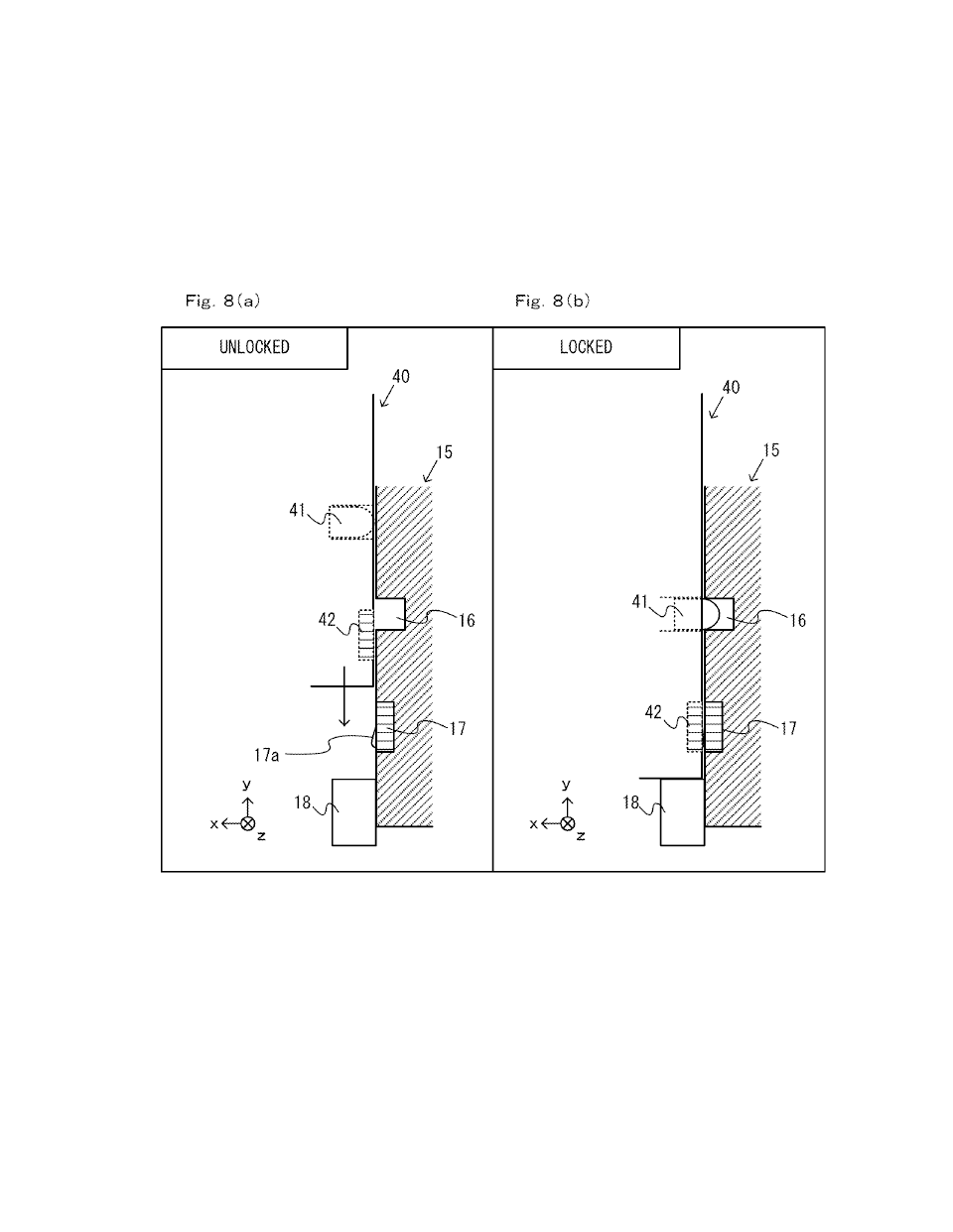
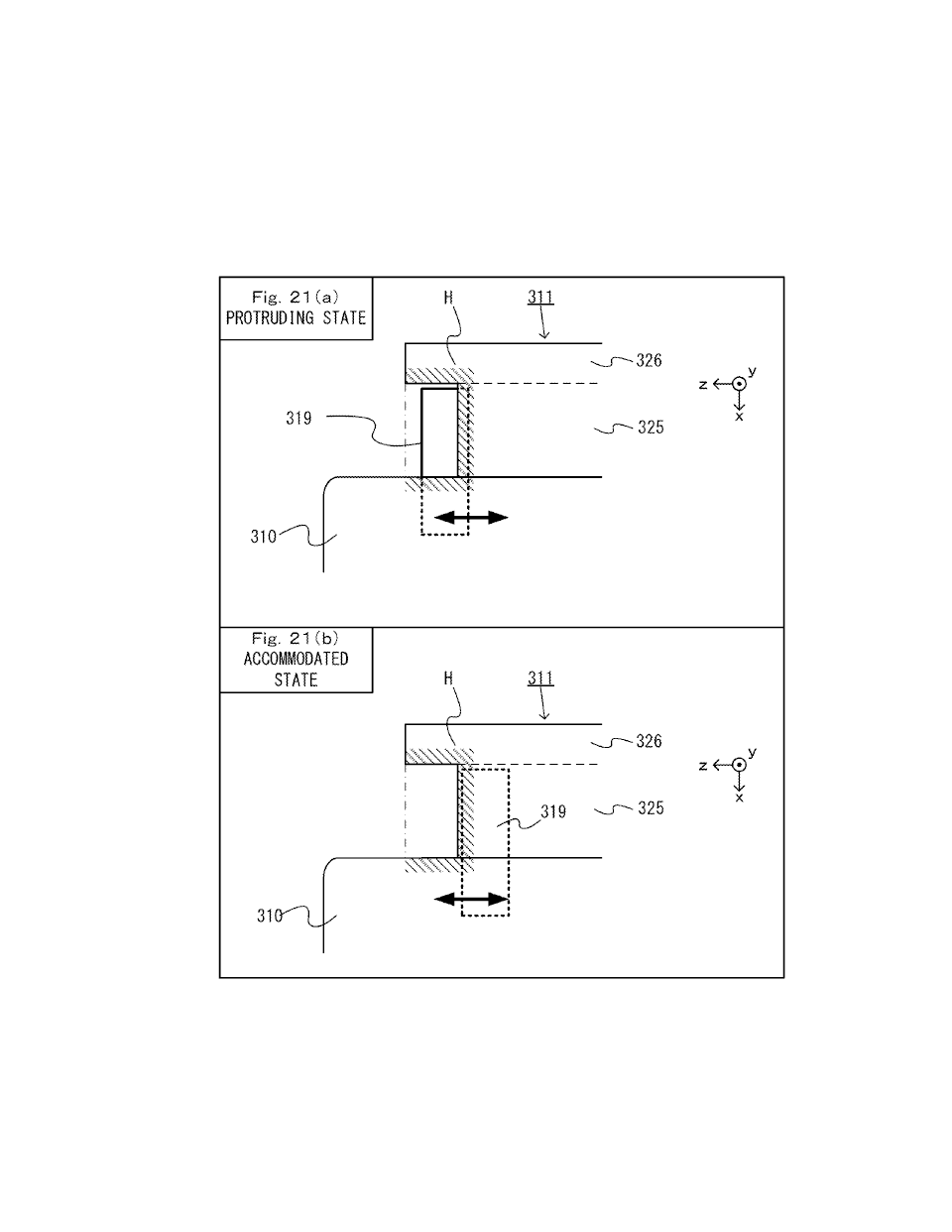
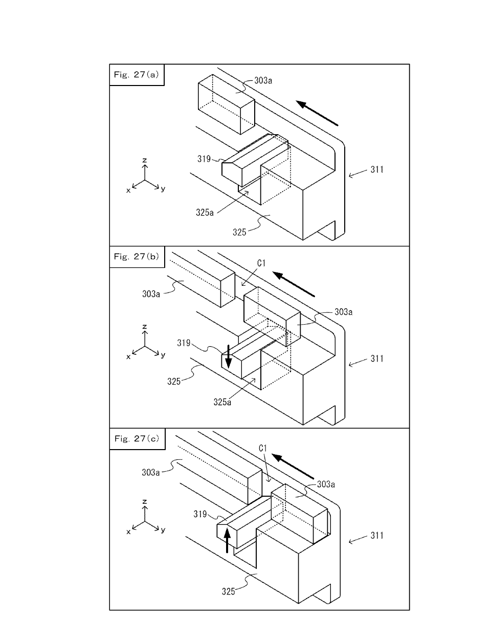
[0891] In the embodiment described above, the game controller further includes a stop member (e.g., the stop member 319 or 339) that resists a slide movement of the controller-side slide member against the main unit-side slide member in a direction opposite to a direction in which the controller-side slide member is inserted into the main unit-side slide member when the controller-side slide member has been inserted up to a predetermined position into the main unit-side slide member (e.g., in the attached state described above). Then, it is possible with the stop member to reduce the possibility that the controller-side slide member comes off the main unit-side slide member.
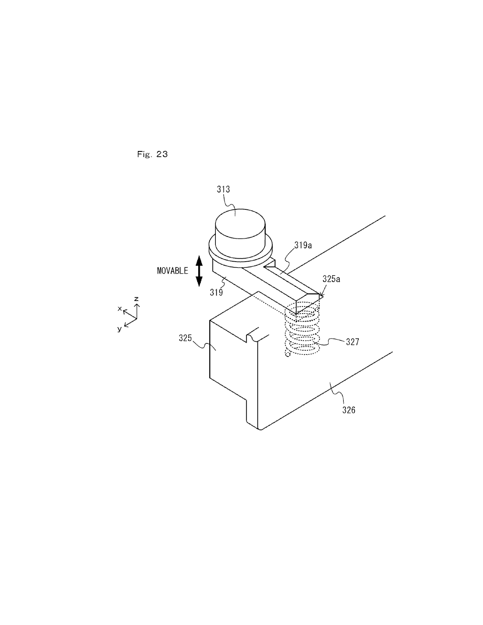
[0892] In the embodiment described above, the game controller further includes a stop member (e.g., the stop member 319 or 339) configured to stop the main unit-side slide member when the controller-side slide member has been inserted up to a predetermined position into the main unit-side slide member (e.g., in the attached state described above), wherein the stop member protrudes from the controller-side slide member in a direction that is perpendicular to the slide direction and parallel to the first surface (e.g., the z-axis direction shown in FIG. 21). Then, it is possible with the stop member to reduce the possibility that the controller-side slide member comes off the main unit-side slide member.
[0893] In the embodiment described above, the stop member is on the second end side (e.g., the upper end side shown in FIG. 14, i.e., the y-axis positive direction side) of a center of the controller-side slide member in the slide direction. Then, the stop member does not come into contact with the main unit unless the controller-side slide member is inserted to a certain degree into the main unit-side slide member, thereby making it less easy for the stop member to come into contact with the main unit. That is, it is possible to make it easier for the controller-side slide member to be moved smoothly into the main unit-side slide member.
[0894] In the embodiment described above, the stop member protrudes from the first surface of the game controller (see FIG. 22) or from a side surface of the controller-side slide member substantially perpendicular to the first surface (see FIG. 21). Then, it is possible to reduce the possibility that the stop member is damaged by being in contact with other objects.
[0895] In the embodiment described above, the terminal is on the facing surface (see FIG. 15, FIG. 16). A surface on a reverse side of the protruding portion of the facing surface comprises a metal member (e.g., the reinforcement member 312 or 332) over at least a part of an area where the terminal is on the facing surface, and a remaining portion of the protruding portion comprises a resin member. Then, it is possible to increase the mechanical strength of the protruding portion (specifically, a portion where the terminal is provided).
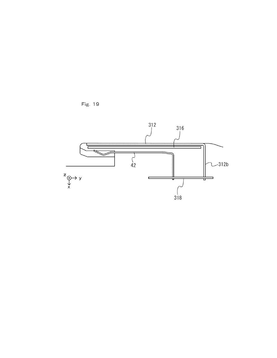
[0896] In the embodiment described above, the game controller further includes an insulator (e.g., the insulation sheet 316) between the terminal and the metal member. Then, it is possible to reduce the possibility that the terminal is electrically affected by the metal member, and it is therefore possible to improve the accuracy of communication between the game controller and the main unit.
[0897] In the embodiment described above, the game controller further includes a water-resisting member (e.g., the insulation sheet 316) between the terminal and the metal member. Then, it is possible to reduce the possibility that water touches the terminal to deteriorate (i.e., rust) the terminal.
[0898] In the embodiment described above, the game controller further includes an electronic circuit (e.g., the electronic circuit 318) including a ground portion (e.g., the ground land portion 318b). The terminal is a ground terminal electrically connected to the ground portion. The metal member further includes a ground connecting portion (e.g., the ground connection portion 312d) electrically connected to the ground portion. Then, it is possible to reduce the possibility of the metal member being electrically charged, and it is therefore possible to reduce the possibility that the terminal is electrically affected by the metal member. It is therefore possible to improve the accuracy of communication between the game controller and the main unit.
[0899] In the embodiment described above, the game controller has side surfaces. The first surface is one of the side surfaces (e.g., the right side surface of the left controller 3 or the left side surface of the right controller 4). The operation section includes a first input section (e.g., the first L button 38, the ZL button 39, the first R button 60 or the ZR button 61) on one of the side surfaces that corresponds to the second end side in the slide direction (e.g., the upper end side shown in FIG. 14, i.e., the y-axis positive direction side). Then, the game controller can easily be attached to the main unit in a case in which a user holds a game controller in such a manner (e.g., the manner shown in FIG. 33) that the first input section is operated using the index finger.
[0900] In the embodiment described above, the controller-side slide member is configured to be inserted into the main unit-side member on at least one of left and right side surfaces relative to a surface of the main unit (e.g., the front surface of the main unit 2) that includes a display (e.g., the display 12) (see FIG. 3) and from an upper side of the main unit-side slide member (see FIG. 2). Then, the game controller can be attached to and detached from the main unit while the main unit is put down, and it is possible to improve the usability of the information processing device including the main unit and the game controller.
[0901] In the embodiment described above, the operation section includes a directional input section (e.g., the analog stick 32 or 52) enabling inputs of at least four directions of up, down, left and right. Thus, the game controller includes a directional input section with which it is possible to easily make directional inputs, thereby improving the input function of the information processing device.
[0902] In the embodiment described above, the directional input section outputs a two-dimensional value representing a direction and a quantity that have been input (e.g., the direction and the magnitude corresponding to the tilt direction and the tilt amount of the stick member of the analog stick). Thus, the game controller includes a directional input section with which it is possible to make detailed directional inputs, thereby improving the input function of the information processing device.
[0903] In the embodiment described above, the directional input section is an input device including an input member (e.g., the stick member of the analog stick) that is configured to be tilted or slid, from a reference position, in at least four directions of up, down, left and right. Thus, the game controller includes a directional input section with which it is possible to more easily make directional inputs, thereby improving the input function of the information processing device.
[0904] In the embodiment described above, the operation section includes a save-an-image input section (e.g., the record button 37) for giving an instruction to save an image being displayed on the display (e.g., the display 12) of the main unit. Thus, the game controller has a function of accepting an input instruction to save an image, thereby improving the usability of the information processing device.
[0905] In the embodiment described above, the game controller further includes an infrared image-capturing device (e.g., the infrared image-capturing section 123). Thus, the game controller has the image-capturing function, thereby improving the usability of the information processing device.
[0906] In the embodiment described above, the operation section includes a second input section (e.g., the second L button 43 or 65, the second R button 44 or 66) on a surface of the controller-side slide member that faces the same direction as the first surface. Then, when the game controller is removed from the main unit, the second input section can be operated, and it is therefore possible to improve the usability of the information processing device. Moreover, an input section that is not used when the game controller is attached to the main unit is provided at such a position that the input section cannot be operated when the game controller is attached to main unit, thereby efficiently using the area of a game controller and efficiently arranging input sections on a game controller.
[0907] (Functions/Effects Regarding Stop Member of Controller)
[0908] In the embodiment described above, a game controller (e.g., the left controller 3 or the right controller 4) is removabley attachable to a main unit (e.g., the main unit 2) having a main unit-side slide member (e.g., the left rail member 300) and configured to execute a game process.
[0909] The game controller includes: [0910] an operation section (e.g., the analog stick 32, 52, the operation buttons 33 to 39, 43, 44, 46, 47, 53 to 61, 65, 66, 69); and [0911] a controller-side slide member (e.g., the slider 311, 331) protruding from a first surface of the game controller and configured to slidably engage with the main unit-side slide member in a slide direction (e.g., the up-down direction shown in FIG. 14, i.e., the y-axis direction).
[0912] The controller-side slide member has a first end and a second end in the slide direction, and the game controller is configured to be attached to the main unit by inserting the controller-side slide member into the main unit-side slide member from the first end (e.g., the lower end of the slider 331 shown in FIG. 14, i.e., the end on the y-axis negative direction side).
[0913] The game controller includes a stop member (e.g., the stop member 319 or 339) configured to resist a slide movement, in an opposite direction, of the controller-side slide member against the main unit-side slide member, the opposite direction being a direction opposite to a direction in which the controller-side slide member is inserted into main unit-side slide member.
[0914] The stop member is configured to protrude from the first surface of the game controller (see FIG. 22) or from a side surface of the controller-side slide member, which side surface is substantially perpendicular to the first surface (see FIG. 21), and the stop member is on the second end side of a center of the controller-side slide member in the slide direction (e.g., on the upper side of the slider 311 shown in FIG. 14).
[0915] Then, it is possible with the stop member to reduce the possibility that the controller-side slide member comes off the main unit-side slide member. Since the stop member is allowed to protrude from the first surface or the side surface of the controller-side slide member, it is possible to reduce the possibility that the stop member is damaged by being in contact with other objects. Moreover, since the stop member is provided on the second end side of the center of the controller-side slide member in the slide direction, it is possible to make it less easy for the stop member to come into contact with the main unit. That is, it is possible to make it easier for the controller-side slide member to be moved smoothly into the main unit-side slide member.
[0916] Note that "the stop member being allowed to protrude from a surface" means to include both the first embodiment in which the stop member may be protruding from a surface (specifically, the protruding state described above) or not protruding from a surface (specifically, the accommodated state described above), and the second embodiment in which the stop member is always protruding from a surface. The second embodiment is for example an embodiment in which the stop member can move between (a) the protruding state described above, and (b) a state in which it is protruding from the surface but is closer to the surface than in the protruding state (in other words, a state in which the stop member is not completely accommodated).
[0917] In the embodiment described above, the stop member is movable between a first position (e.g., the position shown in FIG. 21(a)) and a second position (e.g., the position shown in FIG. 21(b)). The stop member in the first position is more protruding from at least one of the first surface of the game controller and the side surface of the controller-side slide member as compared with the stop member in the second position. The stop member is biased toward a protruding state in the first position. Then, when inserting the controller-side slide member into the main unit-side slide member, the stop member moves into the second position depending on the situation, thereby allowing the controller-side slide member to be inserted smoothly. With the stop member being movable, it is possible to reduce the possibility that the stop member is damaged by being in contact with other objects.
[0918] In the embodiment described above, the stop member is configured to move to a position, as the second position, at which the stop member is in an accommodated state in which the stop member is accommodated inside the game controller (FIG. 21(b)). Then, with the stop member in the accommodated state, the controller-side slide member can be more smoothly inserted into the main unit-side slide member. With the stop member in the accommodated state, it is possible to further reduce the possibility that the stop member is damaged by being in contact with other objects.
[0919] In the embodiment described above, the game controller further includes a movable member (e.g., the release button 313 or 333) that is configured to be moved by an operation by a user, wherein the stop member is moved at least from the first position to the second position in response to the movable member being operated by a user. Then, it is possible, by a user operation, to weaken or release the engagement of the stop member. Thus, a user can easily perform the operation of removing the game controller from the main unit.
[0920] In the embodiment described above, the movable member is biased to be placed at a reference position (e.g., the state shown in FIG. 27(a)), and is configured to move at least from the reference position in response to an operation by a user. The stop member is coupled to the movable member, and the stop member is in the first position when the movable member is placed at the reference position and the stop member comes into the second position in response to the movable member moving from the reference position. Then, since the position of the movable member changes depending on whether the stop member is in the first position or in the second position, a user can recognize the state of the stop member (i.e., whether it is in the first position or in the second position) depending on the position of the movable member.
[0921] In the embodiment described above, the stop member is formed so that at least a portion of an end portion thereof on the first end side in the slide direction (e.g., the end portion having the slope 319a shown in FIG. 23), a thickness of the stop member in a moving direction from the first position to the second position decreases toward a distal end thereof. Then, when inserting the controller-side slide member into the main unit-side slide member, the stop member 319 is unlikely to be interfered by the main unit. Thus, the controller-side slide member can be smoothly inserted into the main unit-side slide member.
[0922] In the embodiment described above, the movable member is on a surface on a reverse side of the front surface (of the game controller) (see FIG. 14). Then, when a user holds the information processing device with the game controller attached to the main unit, the user can easily operate the movable member. Thus, it is possible to provide an information processing device having a high usability and having a movable member that is easy to operate.
[0923] Note that in other embodiments, the movable member may be on the front surface (of the game controller). Then, when a user holds the information processing device with the game controller attached to the main unit, the user can see the movable member. Thus, it is possible to provide an information processing device having a high usability and having a movable member that is easy to operate.
[0924] Note that in other embodiments, the movable member is on both the front surface (of the game controller) and on a surface on a reverse side of the front surface.
[0925] In the embodiment described above, the game controller further includes a projection in the vicinity of the movable member of the game controller, wherein the projection (e.g., the projection portion 314 or 334 and/or the ZL button 39 or the ZR button 61) projects past a surface that the movable member is on. Then, it is possible with the projection to reduce the possibility that the movable member is operated in error. Thus, it is possible to reduce the possibility that the erroneous operation of the movable member releases the engagement of the stop member, resulting in the game controller being removed from the main unit.
[0926] The embodiment described above the projection is a button (i.e., the ZL button 39 or the ZR button 61).
[0927] In the embodiment described above, the game controller includes a depressed portion (e.g., the depressed portion H shown in FIG. 21) defined by the first surface and the controller-side slide member so as to have a C-shaped cross section along a direction perpendicular to the slide direction. The stop member, in the protruding state, protrudes from at least one of surfaces defining the depressed portion (FIG. 21 or FIG. 22). Then, it is possible to reduce the possibility that the stop member is damaged by being in contact with other objects.
[0928] In the embodiment described above, the stop member does not protrude out of a space in the depressed portion into a space outside the game controller in the protruding state (FIG. 21 or FIG. 22). Then, it is possible to further reduce the possibility that the stop member is damaged by being in contact with other objects.
[0929] In the embodiment described above, the stop member is configured to protrude, in a protruded state, from the controller-side slide member in a direction perpendicular to the slide direction and parallel to the first surface (e.g., the z-axis direction shown in FIG. 21). Then, it is possible to reduce the possibility that the stop member is damaged by being in contact with other objects.
[0930] In the embodiment described above, the stop member is at an end portion on the second end side of a center of the controller-side slide member in the slide direction (e.g., the upper end of the slider 311 shown in FIG. 14). This allows the controller-side slide member to be moved more smoothly against the main unit-side slide member.
[0931] In the embodiment described above, the game controller further includes at least one terminal (e.g., the terminal 42 or 46) that is on the first end side (e.g., the lower end side) of the stop member in the slide direction and that is electrically connectable to the main unit. Then, it is possible to reduce the possibility that the stop member comes into contact with the main unit, and it is possible to reduce the possibility that the terminal of the main unit is damaged.
[0932] In the embodiment described above, the terminal is at an end portion on the first end side of the controller-side slide member. Then, it is possible to reduce the possibility that the controller-side slide member comes into contact with the main unit, and it is possible to reduce the possibility that the terminal of the main unit is damaged.
[0933] (Functions/Effects Regarding Operation Sections Provided on Slide Member of Controller)
[0934] In the embodiment described above, a game controller (e.g., the left controller 3 or the right controller 4) is is removably attachable to a main unit (e.g., the main unit 2) having a main unit-side slide member (e.g., the left rail member 300) and configured to execute a game process.
[0935] The game controller includes a controller-side slide member (e.g., the slider 311, 331) protruding from a first surface of the game controller and being configured for slidably engaging with the main unit-side slide member in a slide direction (e.g., the up-down direction shown in FIG. 14, i.e., the y-axis direction).
[0936] The controller-side slide member has first and second ends and includes, as surfaces facing substantially in the same direction as the first surface, a lower surface (e.g., the lower-tier surface 311f shown in FIG. 24) and an upper surface (e.g., the upper-tier surface 311d shown in FIG. 24), a first distance between the lower surface and the first surface being less than a second distance between the upper surface and the first surface, the lower surface extending from the first end to the second end of the controller-side slide member in a direction substantially perpendicular to the slide direction.
[0937] The game controller includes a first operation control (e.g., the second L button 43 or 65 or the second R button 44 and 66 shown in FIG. 14 or FIG. 25) provided on the lower surface, the first operation control being configured so as not to project past the upper-tier surface.
[0938] According to the above description, an input section that is not used when the game controller is attached to the main unit is provided at such a position (i.e., the lower-tier surface) that the input section cannot be operated when the game controller is attached to the main unit. This makes it possible to efficiently use the area of a game controller and efficiently arrange input sections on a game controller. According to the above description, since the first operation control is provided on the lower-tier surface, the controller-side slide member can be slid smoothly against the main unit-side slide member. Moreover, since the lower-tier surface is provided to extend from one end to the other end in the direction substantially perpendicular to the slide direction, it is easier for a user to operate the first operation control.
[0939] In the embodiment described above, the first operation control is configured so as not to protrude past the upper surface. This allows the controller-side slide member to be slid more smoothly against the main unit-side slide member.
[0940] In the embodiment described above, the first operation control extends away from the first surface by a distance greater than the first distance and less than or equal to the second distance. This allows the controller-side slide member to be slid more smoothly against the main unit-side slide member.
[0941] In the embodiment described above, the controller-side slide member has a first end and a second end in the slide direction, and the controller-side slide member includes a first lower surface on the first end side of a center of the controller-side slide member in the slide direction, and a second lower surface on the second end side of the center of the controller-side slide member in the slide direction (FIG. 14, FIG. 25). The first operation control includes a first input section (e.g., the second L button 43 or 65) on the first lower surface, and a second input section (e.g., the second R button 44 and 66) on the second lower surface. Then, when the game controller is removed from the main unit, a user can operate the first input section using one hand, and the second input section using the other hand (FIG. 35). Thus, it is possible to improve the controllability of the game controller.
[0942] In the embodiment described above, the game controller further includes a light-emitter (e.g., the indicator LED 45 or 67) on the upper surface between the first input section and the second input section configured for notifying a user of information. Then, even when the first input section and the second input section are operated by a user, the light-emitting portion is unlikely to be hidden by a hand of the user. That is, it is possible to reduce the possibility that the visibility of the light-emitting portion is reduced when input sections are provided.
[0943] In the embodiment described above, the controller-side slide member defines a sloped surface (e.g., the slope 311e shown in FIG. 24) connecting the lower surface and the upper surface. Then, it is possible to reduce the awkwardness to be felt by a user when operating the first operation control.
[0944] In the embodiment described above, the game controller is configured to be attached to the main unit by engaging the controller-side slide member with the main unit-side slide member.
[0945] The game controller includes: [0946] a light-emitter on the upper surface configured for notifying a user of information; and [0947] a light emission control (e.g., the communication control section 101 or 111) configured for controlling the light-emitter to emit light at least on a condition that the game controller is not attached to the main unit, and for controlling the light-emitter not to emit light when the game controller is attached to the main unit.
[0948] Thus, it is possible to reduce the power consumption of the game controller by controlling the light-emitting portion so that the light-emitting portion does not emit light when there is little need to emit light.
[0949] In the embodiment described above, the game controller further includes a second operation control (e.g., the analog stick 32, 52, the operation buttons 33 to 39, 47, 53 to 61) on a surface (e.g., the front surface or the upper side surface) of the game controller that is different from the first surface. Then, the second operation control can be operated when the game controller is attached to the main unit and when it is removed from the main unit, and it is possible to improve the controllability of the game controller with the provision of such a second operation control on the game controller.
[0950] In the embodiment described above, the second operation control is on a front surface of the game controller. The first surface is a side surface relative to the front surface. Then, a user can operate the first operation control provided on the side surface (e.g., using the index finger) while operating the second operation control provided on the front surface (e.g., using the thumb). Thus, it is possible to provide a game controller having a good controllability when the game controller is removed from the main unit.
[0951] (Functions/Effects Regarding Supporting Device to which Controller can be Attached)
[0952] In the embodiment described above, a supporting device (e.g., the extension grip 350 shown in FIG. 54) is a device for supporting a first game controller (e.g., the left controller 3) and a second game controller (e.g., the right controller 4).
[0953] The first game controller includes a first rail member (e.g., the slider 311) configured for allowing the first game controller to be attached to the supporting device.
[0954] The second game controller includes a second rail member (e.g., the slider 331) configured for allowing the second game controller to be attached to the supporting device.
[0955] The supporting device includes: [0956] a support section (e.g., the support section 352 shown in FIG. 54); and [0957] a main section (e.g., the main section 351 shown in FIG. 54) connected to the support section.
[0958] The support section includes: [0959] a first slide member (e.g., the left rail member 356) in an area of the support section toward a first side in a predetermined direction (e.g., the x-axis positive direction side shown in FIG. 54), the first slide member being configured to slidably engage with the first rail member of the first game controller in a first slide direction; and [0960] a second slide member (e.g., the right rail member 357) in an area of the support section toward a second side in the predetermined direction (e.g., the x-axis negative direction side shown in FIG. 54), the second slide member being configured to slidably engage with the second rail member of the second game controller in a second slide direction.
[0961] The first slide member includes: [0962] a first facing portion (e.g., the opposing portion of the left rail member 356) in the area of the support section toward the first side or on the first slide member, the first facing portion having a first facing surface facing the second side; and [0963] a first terminal (e.g., the left-side terminal 367 provided on the left rail member 356) on the first facing surface, which first terminal is configured to be electrically connected to the first game controller.
[0964] The second slide member includes: [0965] a second facing portion (e.g., the opposing portion of the right rail member 357) in the area of the support section toward the second side or on the second slide member, the second facing portion having a second facing surface facing the first side; and [0966] a second terminal (e.g., the right-side terminal 368 provided on the right rail member 357) on the second facing surface, which second terminal is configured to be electrically connected to the second game controller.