Nintendo Switch USB C Fix New Repair Method

  • Thread starter Thread starter RippedTraces
  • Start date Start date
  • Views Views 13,213
  • Replies Replies 31
  • Likes Likes 11
Will you be adapting the iPad charge flex punch hole design on your flex?
View attachment 300944
Hi,

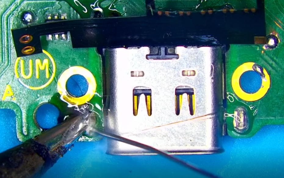
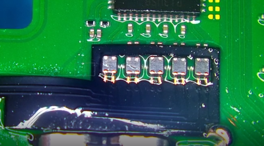
Since the assumption is that the pads on the Nintendo Switch would be torn as shown below, there wouldn't be any pads to solder a punch hole design to. The Nintendo Switch USB C Fix has pads to solder to restore all 24 traces on the Nintendo Switch without the need to run jumper wires. If the iPad flex had one torn trace below, you would need to run a jumper to that flex in order to restore functionality of that ripped trace. If you could explain the reasoning behind the said design we can definitely look into incorporating it.

Thanks

QFqhb1Q.jpeg
 
Hi,

Since the assumption is that the pads on the Nintendo Switch would be torn as shown below, there wouldn't be any pads to solder a punch hole design to. The Nintendo Switch USB C Fix has pads to solder to restore all 24 traces on the Nintendo Switch without the need to run jumper wires. If the iPad flex had one torn trace below, you would need to run a jumper to that flex in order to restore functionality of that ripped trace. If you could explain the reasoning behind the said design we can definitely look into incorporating it.

Thanks

QFqhb1Q.jpeg
I assumed not always 24pads had been ripped off. So most case there are few pads remain(i.e VCC or ground pads) so my theory is reusing them for alignment or re-enforcement for high current drawing heat dissipation. Originally I was wondering if soldering repair flex onto new port prior to solder on mainboard, but it seems not practical from the non-punch whole design lack of pad alignment. Nevertheless, good to see such nice design to support repair community.
 
  • Like
Reactions: RippedTraces
I assumed not always 24pads had been ripped off. So most case there are few pads remain(i.e VCC or ground pads) so my theory is reusing them for alignment or re-enforcement for high current drawing heat dissipation. Originally I was wondering if soldering repair flex onto new port prior to solder on mainboard, but it seems not practical from the non-punch whole design lack of pad alignment. Nevertheless, good to see such nice design to support repair community.
With the iPad Flex, you're applying solder via the punch hole to adhere to the pads below. With this, if it did have the design you would still need to reflow the port on top of it which is likely to melt the solder, unlike the iPad version. But to mention, we're also releasing a model with the port already presoldered on and have done tests with members before release. This way, it's also a much quicker installation for people, especially if they don't feel comfortable reflowing the port on themselves.
 
  • Like
Reactions: jkyoho
I am kinda late to the party but it seem to have sold out and they don't reply to emails and inquiries. is the project dead?
 
  • Like
Reactions: ApodacaP
just so you know, I got charged an unnannounced extra 20€ tax when buying from them
 
Here are the pictures of my (mediocre) installation of the flex pcb. I didn't find the proper soldering tip and didn't clean it up but still it looks worse than it is.
The Github repo is Anercomp/Switch_USB-C_Fix
Please see the third picture for necessary future adjustments of the PCB. Hope this saves one or two switches
IMG-20250916-WA0004.jpg
IMG-20250916-WA0005.jpg
IMG-20250916-WA0006.jpg
IMG-20250916-WA0007.jpg
 
  • Love
  • Like
Reactions: Nephiel and FR0ZN
any hopes on having a similar flex cable for the sdcard?
Post automatically merged:

any hopes we can design a similar flex cable for the sdcard? I've seen many cases where the connector pins break just by unplugging the sd card module but even worse after unsolder the connector sometimes the pads on the moderboard are ripped. There a 7 or 8 nice test pads that could be used to solder a flex there and then the connector on top
 
any hopes on having a similar flex cable for the sdcard?
Post automatically merged:

any hopes we can design a similar flex cable for the sdcard? I've seen many cases where the connector pins break just by unplugging the sd card module but even worse after unsolder the connector sometimes the pads on the moderboard are ripped. There a 7 or 8 nice test pads that could be used to solder a flex there and then the connector on top
Could you give more specific details with images etc?
 
Sometimes a pin comes out when unplugging the sdcard as in here:
1766101857070.png


and when people try to resolder the whole connector i've seem people ripping of the traces
1766102061582.png


so with a solution that the one with the flex pcb with a connector presoldered, someone could solder the pcb only to the correspondent test pads, ground and vcc available nearby with a solder pen instead of a hot gun etc.

1766101776172.png
 

Site & Scene News

Popular threads in this forum