Hardware Backlight voltage(s)?

StefanKrupop

Member
OP
Newcomer
Joined
May 3, 2018
Messages
7
Trophies
0
Age
40
XP
99
Country
Germany
Hi!

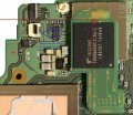
I recently bought a defective Switch from eBay to try and fix it. After fixing the initial problem (Battery was depleted and Switch would not charge. Fixed by replacing the BQ24193 charge controller), it now mainly seems to work fine. However, the screen is really dim even on highest brightness to a point where dark writing is hard to read. The screen itself seems to work fine. See attached photo, the lower one is mine. Both are on max. brightness.
I am now wondering whether a replacement LCD would help or whether the problem is in the backlight driver/LCD driver.

I measured the voltages on the 4 pin backlight connector, referenced to battery ground. However, as I have nothing to compare them to, I do not know whether the voltages are where they should be...
Therefore, I hope that somebody here has his/her Switch already open and would be willing to measure the voltages. Could anybody be so kind, please? Thank you!

Here is what I got (from left to right with game card slot facing towards me):
Backlight on minimum (I am on Firmware 3.0.0): 245 mV - 15.79 V - 261 mV - GND
Backlight on maximum: 247 mV - 16.69 V - 270 mV - GND

I also checked with a scope and saw no signs of the backlight being PWM'ed. I also wonder why 3 pins + GND are used. Does anybody know what they are used for? Some sort of feedback?

Thanks again!

Kind regards,
Stefan

PS: Before replacing the BQ24193, I connected to it's I2C interface and read the registers with an external Raspberry Pi and a level shifter (after I found the STAT pin "blinking" when it should charge). Interestingly, it reported 0x04 in the fault register, which would mean "TS2 Hot". However, this is not even a code mentioned in the datasheet, as both TS1 and TS2 are shorted together in this IC and therefore should be asserted/deasserted at the same time, not individually... I wonder what happened to the controller to cause that...
 

Attachments

  • 20180503_172241.jpg
    20180503_172241.jpg
    87.5 KB · Views: 1,351
Last edited by StefanKrupop,
  • Like
Reactions: SheriffBuck

Xandroz

Well-Known Member
Member
Joined
Mar 19, 2018
Messages
872
Trophies
0
Age
35
XP
1,625
Country
Egypt
hope some tech wiz answers you, but if you want cheap lcd they are on ali express for 10-15 dollars
and good luck fixing it, ita in a really good shape, the one i bought was butchered :D
 

Moquedami

Well-Known Member
Member
Joined
Nov 16, 2006
Messages
436
Trophies
1
XP
1,823
Country
Argentina
Hi! Im having the same problem with a switch not charging. I was wondering how did you find the BQ24193 to be the faulty component? Did yours work when connected in the dock?
I only get a blinking light on the dock, so i was thinking my usbc port or M92T36 where damaged, buy i dont know how to check them.
 

StefanKrupop

Member
OP
Newcomer
Joined
May 3, 2018
Messages
7
Trophies
0
Age
40
XP
99
Country
Germany
I was wondering how did you find the BQ24193 to be the faulty component? Did yours work when connected in the dock?
I currently have no dock (I ordered a defective one :lol: after the Switch is now basically working), so I did not test that before replacing the charging controller. Two days ago I tested my Switch in a friends Dock and it worked fine. I suspect it would also have worked before replacing the BQ24193, minus the charging...

I strongly suspected the BQ24193 being the problem after I found the STAT pin toggling, indicating a charging fault. After I read the status register via I2C I was quite sure it must have been the part, as the indicated fault seemed illegal for this controller.
Also, the voltages present on the charge controller seemed fine, so it got the charging voltage from the USB port. I suspect when the M92T36 was at fault this voltage (VBUS) would probably be missing?

@Xandroz:
Thanks! So far I only looked on eBay and found some there at around 20 €. Will have a look at Ali once I know it's probably not the mainboard but the display/backlight causing the problem.
Indeed, the Switch looks quite good, but I might have paid a relatively high price (77 €) considering that it was just the defective naked console (no Joycons, no Dock, no Power supply) and the "Joycon Gamepad holder thingy"...

Kind regards,
Stefan
 
Last edited by StefanKrupop,

Moquedami

Well-Known Member
Member
Joined
Nov 16, 2006
Messages
436
Trophies
1
XP
1,823
Country
Argentina
Well, i may be able to help you with the voltages measures you need since my switch is already opened. Just keep in mind i only have a multimeter and are tecnically ignorant, so ill need a step by step guide.
 

StefanKrupop

Member
OP
Newcomer
Joined
May 3, 2018
Messages
7
Trophies
0
Age
40
XP
99
Country
Germany
Great, thank you! But please be careful not shorting any pins due to slipping of off one and hitting the adjacent one. I do not want to be the one to blame when your Switch ends up more defective than before... ;)

Mine is currently closed, but I marked some Pins in the picture of the PCB I found at ReSwitched (reswitched.tech/_media/hardware/switchre_side1.jpg). See attachments.

Please put your Multimeter into the "V"(oltage) range. If you have manual ranging, the 20 V range should be fine.
The first picture shows a convenient GND pad where you can place the black probe of your Multimeter. All measurements are referenced to this pin. Also it shows the "STAT" pin of the BQ24193 (on it's pull-up resistor) which might be interesting for your problem. As all parts are _very_ small, make sure to not accidentally short anything. You might want to use the finest probe tips you have...

EDIT: Also interesting to you might be the VBUS voltage. You can measure it on the right hand contact of the brown capacitor left to the arrow in the picture. It should be between 5 and 15 Volts when the power supply is connected (I assume).

The second picture shows the backlight connector. It has 4 pins. When the connector is closed, it might be easiest to probe the pins from the top, between the white and black plastic.

Thank you again!

Kind regards,
Stefan
 

Attachments

  • Stat pin BQ24193.jpg
    Stat pin BQ24193.jpg
    133.2 KB · Views: 1,741
  • Switch backlight pins.jpg
    Switch backlight pins.jpg
    141 KB · Views: 1,856
Last edited by StefanKrupop,

Moquedami

Well-Known Member
Member
Joined
Nov 16, 2006
Messages
436
Trophies
1
XP
1,823
Country
Argentina
Cool, i'll try this in a couple of hours and report back
Noob question, should i messure this points with the battery connected and no power supply?
 
Last edited by Moquedami,

StefanKrupop

Member
OP
Newcomer
Joined
May 3, 2018
Messages
7
Trophies
0
Age
40
XP
99
Country
Germany
should i messure this points with the battery connected and no power supply?
For the BQ24193, the battery and charger should be plugged in.
For the backlight, the Switch should be on and the backlight either turned to min or max. You can see the backlight slightly from the back of the Switch through a hole nearby the connector on the PCB. Please make sure it is still on while you take the readings.

Kind regards,
Stefan
 

Moquedami

Well-Known Member
Member
Joined
Nov 16, 2006
Messages
436
Trophies
1
XP
1,823
Country
Argentina
Sorry pal, i really did my best but those points are just too small, i dont have the proper equipment to do it.
I tried attaching a really small cable at the point of the multimeter to use that, but without a magnifing glass and my pulse I wont make it.
 

StefanKrupop

Member
OP
Newcomer
Joined
May 3, 2018
Messages
7
Trophies
0
Age
40
XP
99
Country
Germany
I just played around with homebrew and tried "tetriswitch". There I noticed the display seems to have more problems than just backlight, see attached picture... :O
Does anybody have an idea whether this is more likely to be caused by the display (respectively the controller built into the display) or by the Motherboard? I suppose the display in the Switch uses the DSI port of the Tegra? Is there any active component between the X1 and the display?

Kind regards,
Stefan
 

Attachments

  • 20180506_222249.jpg
    20180506_222249.jpg
    95.3 KB · Views: 888

StefanKrupop

Member
OP
Newcomer
Joined
May 3, 2018
Messages
7
Trophies
0
Age
40
XP
99
Country
Germany
Just to update you with the final result:
I went ahead and bought the cheapest LCD for the switch I could find off of eBay (19,96 €).
It today arrived and after installing it, I indeed can say the mainboard seems to be fine and the problem was caused by the display:

20180602_233450.jpg

The "ghosting" is now gone and the display is much brighter. I suspect it might have original brightness, but I have no other switch to compare to. However, it looks totally fine to me.

As far as I can say, my Switch is now complete and working fine. Because I had bad luck and it had two defects (charge controller and LCD), I had to pay more to complete it than hoped. In total, it cost me 188,25 € (including 32,66 € that went into the diverse shipments...). However, this is still ~110 € less than if I now would buy a new one...

Kind regards,
Stefan
 

Sidoreczekziom

New Member
Newbie
Joined
Mar 6, 2019
Messages
3
Trophies
0
Age
33
XP
56
Country
United Kingdom
Hi Stefan maby you or someone you guys help me with my switch.. basically i dont have backlight. My pins is showing gnd 0v 3,5v 0v can you help me solve this problem?
 
  • Like
Reactions: SheriffBuck

SheriffBuck

Well-Known Member
Newcomer
Joined
Jan 6, 2020
Messages
98
Trophies
0
Location
Hampton, London
XP
421
Country
United Kingdom
Hi Stefan maby you or someone you guys help me with my switch.. basically i dont have backlight. My pins is showing gnd 0v 3,5v 0v can you help me solve this problem?

I've had this happen to me with a couple of units in for repair. It's either the backlight controller IC which can be replaced with a TPS61163A (Search for this part number in this forum and you'll find more detail and pictures), or the backlight itself which is very sensitive to water damage as the backlight is driven with 16-17v which is a magnet for water deposits and corrosion.

The only solution for the latter is to replace the LCD module - fortunately these aren't that expensive if you shop around on eBay and there are plenty of great instruction videos.

Do you have another board you can swap out and confirm if it's the backlight or the backlight controller?

--------------------- MERGED ---------------------------

I also checked with a scope and saw no signs of the backlight being PWM'ed. I also wonder why 3 pins + GND are used. Does anybody know what they are used for? Some sort of feedback?

Stefan - The backlight has a voltage supply "drive" line (typically 16v when working) and two current-control "drain" lines. The controller works by regulating the return current rather than the supply current. This is split across two channels in a balanced fashion.

The backlight connector has 4 pins, however one pin is redundant. Judging by the number of failures with the drive pin burning out, it would have been better sense to have used the redundant pin as another drive pin.

Sheriff.
 
  • Like
Reactions: Ttm3

Site & Scene News

Popular threads in this forum

General chit-chat
Help Users
  • BakerMan @ BakerMan:
    guys, pubg should've never blown up
  • BigOnYa @ BigOnYa:
    Wut do you mean? Pubg is alright, I play it with a few buddies online.
  • BakerMan @ BakerMan:
    the game itself is ok, but it's influence is the problem
  • K3Nv2 @ K3Nv2:
    Call of duty is a good Fortnite skin
  • BakerMan @ BakerMan:
    call of duty and fortnite, ex-fucking-actly
  • BakerMan @ BakerMan:
    without pubg popping off, fortnite wouldn't add battle royale, and call of duty wouldn't go even shittier than it did before because of blackout, warzone and dmz
  • Psionic Roshambo @ Psionic Roshambo:
    Make a porn based spoof of it, Pube G
  • BigOnYa @ BigOnYa:
    Just play My Pony online. Its better than Fortnight or COD.
  • Psionic Roshambo @ Psionic Roshambo:
    FPS porn games sound fun lol
    +1
  • K3Nv2 @ K3Nv2:
    Call of duty got close with that by using Nikkie Minaj
  • BigOnYa @ BigOnYa:
    -Bonus- Faceshot
  • K3Nv2 @ K3Nv2:
    5 killstreak call in the gangbang
    +1
  • Psionic Roshambo @ Psionic Roshambo:
    Still enjoying Bad Ass Babes lol
  • Psionic Roshambo @ Psionic Roshambo:
    Legit a super solid beat em up
  • Psionic Roshambo @ Psionic Roshambo:
    The special moves are hilarious
  • BigOnYa @ BigOnYa:
    Introducing the most anticipated 1p v 4p game of the year - COCC (Call of couch casting)
    +1
  • RetroNerdGamer @ RetroNerdGamer:
    isnt that just gal gun
    +1
  • K3Nv2 @ K3Nv2:
    Hoochie gun
    +1
  • K3Nv2 @ K3Nv2:
    Rain again
    +1
  • BigOnYa @ BigOnYa:
    Yea been raining here on off all day, had 1\4" hail earlier even.
  • K3Nv2 @ K3Nv2:
    Think I heard some hail outside
  • Veho @ Veho:
    Who are they hailing?
  • K3Nv2 @ K3Nv2:
    My mom probably
    +1
  • K3Nv2 @ K3Nv2:
    People care about this being free for some reason https://store.epicgames.com/en-US/p/farming-simulator-22
    K3Nv2 @ K3Nv2: People care about this being free for some reason...