Hi guys,
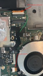
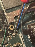
I screwed up my HW FLY installation somewhere and now my switch is not turning on. I never managed to get any lights to turn on the mod chip and I also cannot get it to boot into stock now. Essentially pressing the power button does nothing. My battery is showing 4.14V, which I was told is near / full charge. Based on research I found the most likely culprit it somewhere in my nand installation. These are all of my multimeter values.
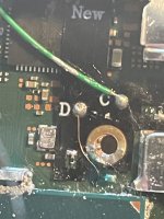
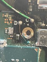
D = .722
C = .683
A = .458
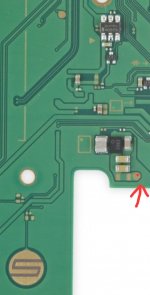
Nand wire - .685
Nand anchor - OL (reverse = .682 (positive on ground))
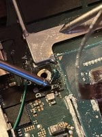
I understand in the photos that I grossly over thermal pasted but I've cleaned that up now and will be more careful moving forward. I checked all my points for shorts and nothing appears to be shorted that I can find. I'm hoping I haven't completely screwed myself and am looking for possible solutions. I will likely be taking it to a professional here on out if there is anything to be done.


I screwed up my HW FLY installation somewhere and now my switch is not turning on. I never managed to get any lights to turn on the mod chip and I also cannot get it to boot into stock now. Essentially pressing the power button does nothing. My battery is showing 4.14V, which I was told is near / full charge. Based on research I found the most likely culprit it somewhere in my nand installation. These are all of my multimeter values.
D = .722
C = .683
A = .458
Nand wire - .685
Nand anchor - OL (reverse = .682 (positive on ground))
I understand in the photos that I grossly over thermal pasted but I've cleaned that up now and will be more careful moving forward. I checked all my points for shorts and nothing appears to be shorted that I can find. I'm hoping I haven't completely screwed myself and am looking for possible solutions. I will likely be taking it to a professional here on out if there is anything to be done.