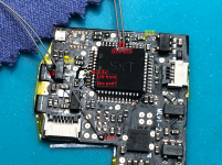
Tutorial  Updated

How to flash the HWFLY Clone chips

See below for updates.

IF YOU BREAK YOUR BOOT0 PIN. DO NOT DM ME ASKING FOR HELP. THAT'S IT. YOU BREAK THAT PIN AND YOU CANT FLASH. YOUR CHIP IS STUCK WITH WHATEVER HWFLY PUT ON IT


Pre-requisites:


  • Raspberry Pi Zero W
    • You may use another flasher if you desire.
  • Pinout Diagram
  • Modchip Diagram
  • FULL_CHIP_STOCK.bin
  • Modchip Diagram, find the PA9(TX) and the PA10(RX) pins on your modchip, and do the following:
    • Connect GPIO14(TX) on your Raspberry Pi Zero W to the PA10(RX) pin on your modchip.
    • Connect GPIO15(RX) on your Raspberry Pi Zero W to the PA9(TX) pin on your modchip.

  1. Solder a wire to each of the following pinouts on the Raspberry Pi Zero W:
    • 3.3V
    • Ground
    • GPIO 14 (UART TX)
    • GPIO 15 (UART RX)
  2. Do the following to prepare the modchip:
    1. Lift pin 44 (also known as BOOT0).
    2. You will need a way to power the chip, so you need to find two 3.3v points. It can be on a MOSFET, but it will differ based on the revision of the modchip.
    3. Connect Ground on your Raspberry Pi Zero W to the Ground pin on your modchip.
    4. Check the Modchip Diagram, find the PA9(TX) and the PA10(RX) pins on your modchip, and do the following:
      • Connect GPIO14(TX) on your Raspberry Pi Zero W to the PA10(RX) pin on your modchip.
      • Connect GPIO15(RX) on your Raspberry Pi Zero W to the PA9(TX) pin on your modchip.
  3. Boot your Raspberry Pi Zero W and do the following:
    1. In the terminal, type the following command, and press enter:
      Bash:
      sudo nano /boot/config.txt
    2. Add the following line to the end of the file:
      INI:
      dtoverlay=pi3-miniuart-bt
    3. Press CTRL + X to save and exit the editor.
    4. In the terminal, type the following command, and press enter:
      Bash:
      sudo nano /boot/cmdline.txt
    5. Remove the following line from the file:
      INI:
      console=serial0,115200
    6. Press CTRL + X to save and exit the editor.
    7. Restart your Raspberry Pi with this command
      Bash:
      sudo /sbin/reboot
    8. In the terminal, type the following commands, and press enter after each command:

      Bash:
      git clone https://github.com/Pheeeeenom/stm32flash.git
      cd stm32flash
      sudo make install
  4. Now you will flash the modchip.
    Note: This will remove read protection, and the modchip will wipe itself (that is what we want).
    1. In the terminal, type the following command, and press enter:
      Bash:
      stm32flash -k /dev/serial0
    2. Now to flash Spacecraft-NX Version 0.2.0, type the following, and press enter:
      Bash:
      stm32flash -v -w ./FULL_CHIP_STOCK.bin /dev/serial0
  5. Once you're done flashing your modchip, remove the wiring from the modchip, and restore the 3.3v pin on the modchip to its original position.

Please post pictures of your work here to further the identification of the different board revisions!


UPDATE: So it seems like stitching the spacecraft bootloader and firmware together from the repo causes unstable glitching behaviors. For now, consistent glitching behavior works with this bootload/firmware combo.
This is the original file on the OLED variant chip which has 0.2.0 spacecraft. As for glitching, I'll figure it out, give me some time...unless someone else wants to hop in and reverse the differences.

For now, this at least solves the 0.1.0 HWFLY gen 3 issue. More to come.

UPDATE 2: This is only going to work on some HWFLY chips. Older ones use higher protection than the new revisions that seem to use the QFN FPGA.

UPDATE 3: This should fully work on OLED modchips with the QFN FPGA. https://github.com/Pheeeeenom/firmware
 
Last edited by Mena,

james194zt2

Well-Known Member
Newcomer
Joined
Jan 4, 2022
Messages
57
Trophies
0
Age
42
XP
165
Country
United Kingdom
@james194zt2 I'm starting to think the newer batch of clones are the ones with less protection. @sean222 is sending me his lite for me to work on
Ah joy!! Mine is a core labelled as "v3" by the seller as it's not even a month old, I just wanted to get into it for the challenge and with the hope of debugging it and being able to play with the firmware to look at this sleep issue it seems to have.
 

Mena

Well-Known Member
OP
Member
Joined
Oct 5, 2020
Messages
148
Trophies
0
Age
29
XP
1,032
Country
United States
Ah joy!! Mine is a core labelled as "v3" by the seller as it's not even a month old, I just wanted to get into it for the challenge and with the hope of debugging it and being able to play with the firmware to look at this sleep issue it seems to have.
What kind of FPGA does yours have? it seems like the ones with QFN are the ones with protection mode one enabled. I have some more info to post in a bit
 

mvmiranda

Well-Known Member
Member
Joined
Oct 29, 2013
Messages
1,457
Trophies
1
Location
Brazil, Sao Paulo
Website
www.gamemod.com.br
XP
1,673
Country
Brazil
To those who don't want to solder directly to PA10 and PA9 afraid of shorting he CI legs together I've found possible alternate points for them on a Lite chip (yellow markings).
Lite - Solder Points21.png

I'm getting the timeout error.
I'll double check my wiring.

Image is a courtesy of @Sandmann :)
 
  • Like
Reactions: lufeig

Mena

Well-Known Member
OP
Member
Joined
Oct 5, 2020
Messages
148
Trophies
0
Age
29
XP
1,032
Country
United States
OKAY SO....this is going to get a little technical.

the GD32 line has 3 levels of protection.

First of which is no protection
Second is level one protection which is set when the option bytes are set to anything other than 0xA55A. In this protection mode, there are no vulnerabilities to access the flash by executing CPU instructions over a debugger
The third is level 2. This mode COMPLETELY DISABLES ALL DEBUG INTERFACES. In this mode you cannot do anything. At this point the only attack vector is an invasive attack on the die to expose bonding wires that connect the flash die and the logic die together. At this point you need to expose the IO2 bonding wire of the QSPI communication bus between the 2 dies and glitch it at the precise time that it loads the option bytes from 0x400(factory config) instead of 0x4000. You'd need to glitch a glitch chip lol.

Anyways, it's not viable in a timely manner to do this. It'd be MUCH easier to replace the GD32 and reverse the changes they've made to spacecraft and apply it to vanilla spacecraft.

If you want to know the technical details of the attack: https://www.usenix.org/system/files/woot20-paper-obermaier.pdf and look at point 7.3
 

mjd515

Member
Newcomer
Joined
Sep 23, 2010
Messages
6
Trophies
0
XP
41
Country
United States
OKAY SO....this is going to get a little technical.

the GD32 line has 3 levels of protection.

First of which is no protection
Second is level one protection which is set when the option bytes are set to anything other than 0xA55A. In this protection mode, there are no vulnerabilities to access the flash by executing CPU instructions over a debugger
The third is level 2. This mode COMPLETELY DISABLES ALL DEBUG INTERFACES. In this mode you cannot do anything. At this point the only attack vector is an invasive attack on the die to expose bonding wires that connect the flash die and the logic die together. At this point you need to expose the IO2 bonding wire of the QSPI communication bus between the 2 dies and glitch it at the precise time that it loads the option bytes from 0x400(factory config) instead of 0x4000. You'd need to glitch a glitch chip lol.

Anyways, it's not viable in a timely manner to do this. It'd be MUCH easier to replace the GD32 and reverse the changes they've made to spacecraft and apply it to vanilla spacecraft.

If you want to know the technical details of the attack: https://www.usenix.org/system/files/woot20-paper-obermaier.pdf and look at point 7.3
so with that said, what would that entail to replace the chip, obviously the soldering portion but past that would it be a simple connect via usb and flash youre good to go?
 

Mena

Well-Known Member
OP
Member
Joined
Oct 5, 2020
Messages
148
Trophies
0
Age
29
XP
1,032
Country
United States
so with that said, what would that entail to replace the chip, obviously the soldering portion but past that would it be a simple connect via usb and flash youre good to go?
No, it's a blank chip. You'd need to do the method described in the first post to actually program it. You could use other means such as SWD as well. You would also need to know the difference in the FPGA code and apply them to spacecraft's code. Then you can simply flash it.
 

james194zt2

Well-Known Member
Newcomer
Joined
Jan 4, 2022
Messages
57
Trophies
0
Age
42
XP
165
Country
United Kingdom
No, it's a blank chip. You'd need to do the method described in the first post to actually program it. You could use other means such as SWD as well. You would also need to know the difference in the FPGA code and apply them to spacecraft's code. Then you can simply flash it.
Joyyyyy!!! Back to my original plan A then :( oh well the chips are already enroute from China to replace it, but this was worth a shot :)
 

james194zt2

Well-Known Member
Newcomer
Joined
Jan 4, 2022
Messages
57
Trophies
0
Age
42
XP
165
Country
United Kingdom
FYI leaving BOOT0 pin 44 floating seems to affect the boot time, I am assuming it is probably a timeout waiting for a voltage or ground to be applied maybe? Either way it might explain the glitch time issue you saw on your post if people haven't put it back down, it has added maybe 5 seconds to my glitch time and it now sometimes times out, put it back down and my glitch time is back to 2-3 flashes.

I was being lazy just in case somebody finds some magic that needed it to be lifted again!
 
Last edited by james194zt2,

Mena

Well-Known Member
OP
Member
Joined
Oct 5, 2020
Messages
148
Trophies
0
Age
29
XP
1,032
Country
United States
FYI leaving BOOT0 pin 44 floating seems to affect the boot time, I am assuming it is probably a timeout waiting for a voltage or ground to be applied maybe? Either way it might explain the glitch time issue you saw on your post if people haven't put it back down, it has added maybe 5 seconds to my glitch time and it now sometimes times out, put it back down and my glitch time is back to 2-3 flashes.

I was being lazy just in case somebody finds some magic that needed it to be lifted again!
This is bizarre. I will test it
 
  • Like
Reactions: mvmiranda

james194zt2

Well-Known Member
Newcomer
Joined
Jan 4, 2022
Messages
57
Trophies
0
Age
42
XP
165
Country
United Kingdom
This is bizarre. I will test it
It is strange, I was getting probably a 70/30 hit rate success/failure I rebooted 20+ times or so and it failed at least 5 of them times, whereas it has only ever timed out once maybe twice in all the reboots I have done since installation (there have been a lot!) now I have resoldered it down it is now back to its normal behaviour and I have rebooted loads of times just to check.
 

Mena

Well-Known Member
OP
Member
Joined
Oct 5, 2020
Messages
148
Trophies
0
Age
29
XP
1,032
Country
United States
It is strange, I was getting probably a 70/30 hit rate success/failure I rebooted 20+ times or so and it failed at least 5 of them times, whereas it has only ever timed out once maybe twice in all the reboots I have done since installation (there have been a lot!) now I have resoldered it down it is now back to its normal behaviour and I have rebooted loads of times just to check.
Question is this a clone with a QFN chip that you reflashed? What is the context here
 

sthetix

Well-Known Member
Newcomer
Joined
Dec 25, 2015
Messages
48
Trophies
0
Age
47
XP
874
Country
Indonesia
No dice.
All seems fine but I'm always getting a timeout issue!
1642054708881.png


I'm trying to flash the hwfly lite with RPI and it didn't work.
SWD connection using the GD-programmer / the ST-Link didnt work either. Yes I've lifted pin 44

FYI, as soon as we connect the chip to the RPI, the LED starts blinking purple, red, and off.
 

Attachments

  • Untitled Project.mp4
    1.9 MB
  • Like
Reactions: leerz

Dean_

Well-Known Member
Member
Joined
Sep 11, 2014
Messages
684
Trophies
0
XP
712
Country
I'm trying to flash the hwfly lite with RPI and it didn't work.
SWD connection using the GD-programmer / the ST-Link didnt work either. Yes I've lifted pin 44

FYI, as soon as we connect the chip to the RPI, the LED starts blinking purple, red, and off.
I guess you didn't connect 3.3v line to the lifted pin 44 (set BOOT0 high)
 
Last edited by Dean_,

james194zt2

Well-Known Member
Newcomer
Joined
Jan 4, 2022
Messages
57
Trophies
0
Age
42
XP
165
Country
United Kingdom
View attachment 293507

I'm trying to flash the hwfly lite with RPI and it didn't work.
SWD connection using the GD-programmer / the ST-Link didnt work either. Yes I've lifted pin 44

FYI, as soon as we connect the chip to the RPI, the LED starts blinking purple, red, and off.
Mine did the above, but I think as stated no BOOT0 connection to 3.3v, mine flashes red for a second or 2 when plugged in which I think signals that it is using BOOT0, but I get the above error when attempting to flash. But that is because it is one of the level 2 protected GD32 so can't be reprogrammed sadly.
 
  • Like
Reactions: sthetix

james194zt2

Well-Known Member
Newcomer
Joined
Jan 4, 2022
Messages
57
Trophies
0
Age
42
XP
165
Country
United Kingdom
Out of interest, has the firmware and bootloader for the 0.1 HWFly core been dumped somehow? Was going to try and dump it over the weekend (GD32 vs ChipWhisper to glitch the level 2 flag), but wondered if we already had it to have a look inside?

I am assuming it is in the BOOT0 file due to the tool to compare if it is 0.1 or 0.2 Spacecraft as well? but is it complete and I am doubting it includes the bootloader even if it is in there.
 

Site & Scene News

Popular threads in this forum

General chit-chat
Help Users
    Sicklyboy @ Sicklyboy: 112TB in this photo 😎😎