Hi,
This morning I had some kind of idea under the shower...
A weak point of the USB C port is that it is soldered directly to the motherboard. The exchange is only possible with hot air and the risk that the motherboard takes additional damage. Over the lifetime of your switch you may want to replace the port several times if it gets defective again. Each time you risk your mainboard again.
In other mobile devices these critical components are located on a separate board which is connected to the mainboard with a ribbon cable. In Lenovo ThinkPads, for example, the power socket is very easy to replace in this way.
My question now is whether there is enough space above the USB socket to mount it upside down with a flexboard. I have prepared some very basic concept drawings. The flexboard would have through-holes to solder it to the PCB and then onto the usb port.
If my idea would work, replacing a defective port would work like this:
1) The connector can be carefully crushed out with pliers until the pins are free.
2) Use a solderiron to remove the pins from the switch PCB
3) Solder on the flexboard onto the Switch PCB
4) Solder in two small copper plates
5) Align the USB port upside-down between the copper plates, so that it later fits into the dock
6) secure it by soldering it onto the copper plates
7) Bend the flexboard onto the pins of the usb port and solder it in place
Advantages
Simple assembly and in the future only the flex board will be soldered, not the motherboard.
Disadvantage
Alignment of the usb port may be a little bit more tricky to hits the dock in correct angle
Maybe also the mechanical stability is not as robust as in original
Risks
USB 1 und 2 war immer etwas empfindlich, wenn in der Führung der Leiterbahnen etwas verändert wurde. Beim Design von Platinen sollten zum Beispiel Durchkontaktierungen vermieden werden, damit es zu keinen Störungen kommt. Ihr kennt das, dass manche Geräte mit langen USB Kabeln nicht zurecht kommen, das wäre solch ein Effekt.
There will be no problems loading the switch, but it is possible that the TV output may not always work properly. This should be shown in a practical test.
My personal background:
I am an electrical engineer, I have already designed many boards for microcontrollers, routed and etched them myself. I have not yet developed flex conductors myself. I'd have to get used to this for me new topic.
I usually do 3D designs with FreeCad, this may also help for further development.
What I would need:
- Information about the space above the usb port (maybe there are some 3D models in the web of replacement Switch cases we could use)
- Exact design or 3D model of the original USB port
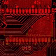
- scan of the Switch PCB to design the flexboard onto it for easy soldering
Regards
sImasC
This morning I had some kind of idea under the shower...
A weak point of the USB C port is that it is soldered directly to the motherboard. The exchange is only possible with hot air and the risk that the motherboard takes additional damage. Over the lifetime of your switch you may want to replace the port several times if it gets defective again. Each time you risk your mainboard again.
In other mobile devices these critical components are located on a separate board which is connected to the mainboard with a ribbon cable. In Lenovo ThinkPads, for example, the power socket is very easy to replace in this way.
My question now is whether there is enough space above the USB socket to mount it upside down with a flexboard. I have prepared some very basic concept drawings. The flexboard would have through-holes to solder it to the PCB and then onto the usb port.
If my idea would work, replacing a defective port would work like this:
1) The connector can be carefully crushed out with pliers until the pins are free.
2) Use a solderiron to remove the pins from the switch PCB
3) Solder on the flexboard onto the Switch PCB
4) Solder in two small copper plates
5) Align the USB port upside-down between the copper plates, so that it later fits into the dock
6) secure it by soldering it onto the copper plates
7) Bend the flexboard onto the pins of the usb port and solder it in place
Advantages
Simple assembly and in the future only the flex board will be soldered, not the motherboard.
Disadvantage
Alignment of the usb port may be a little bit more tricky to hits the dock in correct angle
Maybe also the mechanical stability is not as robust as in original
Risks
USB 1 und 2 war immer etwas empfindlich, wenn in der Führung der Leiterbahnen etwas verändert wurde. Beim Design von Platinen sollten zum Beispiel Durchkontaktierungen vermieden werden, damit es zu keinen Störungen kommt. Ihr kennt das, dass manche Geräte mit langen USB Kabeln nicht zurecht kommen, das wäre solch ein Effekt.
There will be no problems loading the switch, but it is possible that the TV output may not always work properly. This should be shown in a practical test.
My personal background:
I am an electrical engineer, I have already designed many boards for microcontrollers, routed and etched them myself. I have not yet developed flex conductors myself. I'd have to get used to this for me new topic.
I usually do 3D designs with FreeCad, this may also help for further development.
What I would need:
- Information about the space above the usb port (maybe there are some 3D models in the web of replacement Switch cases we could use)
- Exact design or 3D model of the original USB port
- scan of the Switch PCB to design the flexboard onto it for easy soldering
Regards
sImasC
Attachments


Last edited by sImasC,