Tutorial
Updated
Internal modchip - SAMD21 (Trinket M0, Gemma M0, ItsyBitsy M0 Express) Guide, Files & Support
Notice: I am not receiving notifications for this thread. I didn`t realise people were still posting in it.
Please please accept my apologies if I haven`t replied to tags etc... I have no idea what is happening. I`m subscribed to this thread but I am not receiving notifications. Please inbox me if possible. Or tag me in another thread.
Its amazing that people are still checking all of this out. I thank you for all of the help and support I have received in this thread over this year.
Cheers. Matty.
A video showing a modchip in action. Thank you once again to @metaljay for providing this. This is what you can achieve by fitting a chip!
Replacement Parts List
Please please accept my apologies if I haven`t replied to tags etc... I have no idea what is happening. I`m subscribed to this thread but I am not receiving notifications. Please inbox me if possible. Or tag me in another thread.
Its amazing that people are still checking all of this out. I thank you for all of the help and support I have received in this thread over this year.
Cheers. Matty.
A video showing a modchip in action. Thank you once again to @metaljay for providing this. This is what you can achieve by fitting a chip!
Section 1. Gather your software.
Get your chip software from THIS THREAD.
Follow the flashing instructions there...
Get your chip software from THIS THREAD.
Follow the flashing instructions there...
Section 2. Removing USB port and unneeded LEDs. (Adafruit chips only)
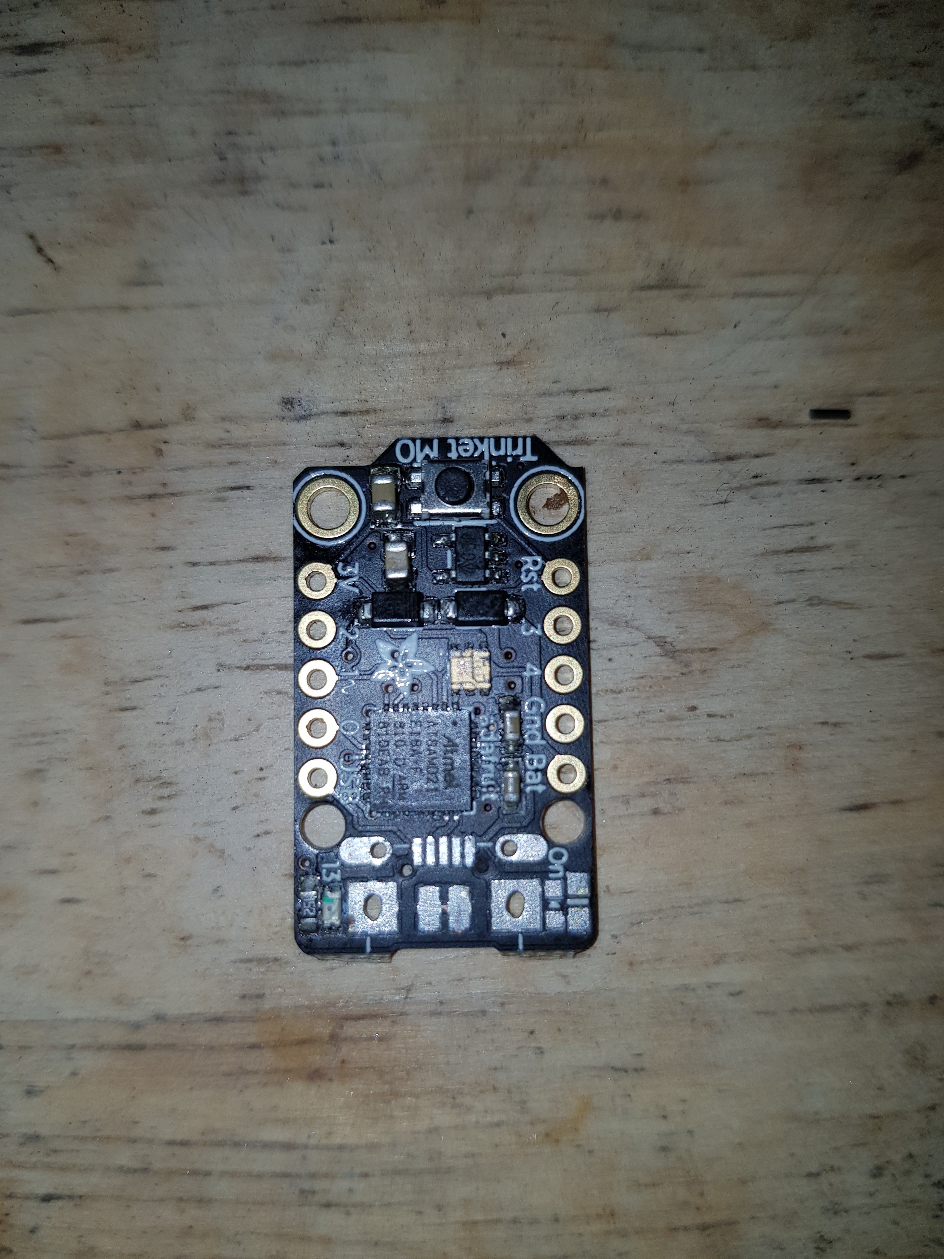
You are now ready to fit your device. Proceed to Fitting section.
- Next, we need to remove the USB port from the modchip. I recommend a heatgun or a rework station. Heat up until the USB port just lifts off the modchip.
- Do the same for the LED just to the right of the USB port.
You are now ready to fit your device. Proceed to Fitting section.
Section 3. Fitting modchip to your Switch.
New Universal Method. All SAMD-based internal chips. If your chip is not supported and you cannot work it out, PM me.
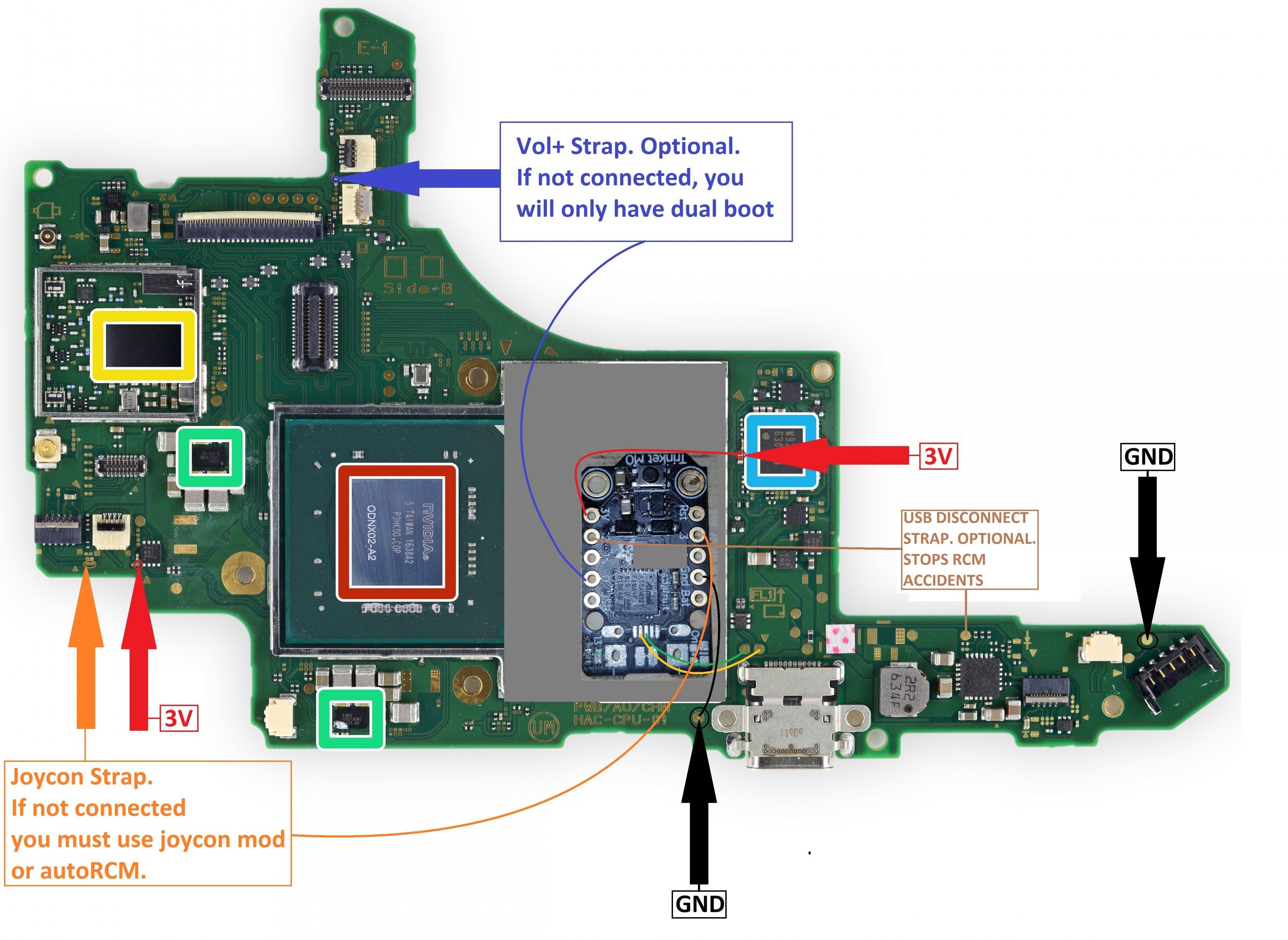
Trinket M0.
Solder as laid out in the following picture
==================================================
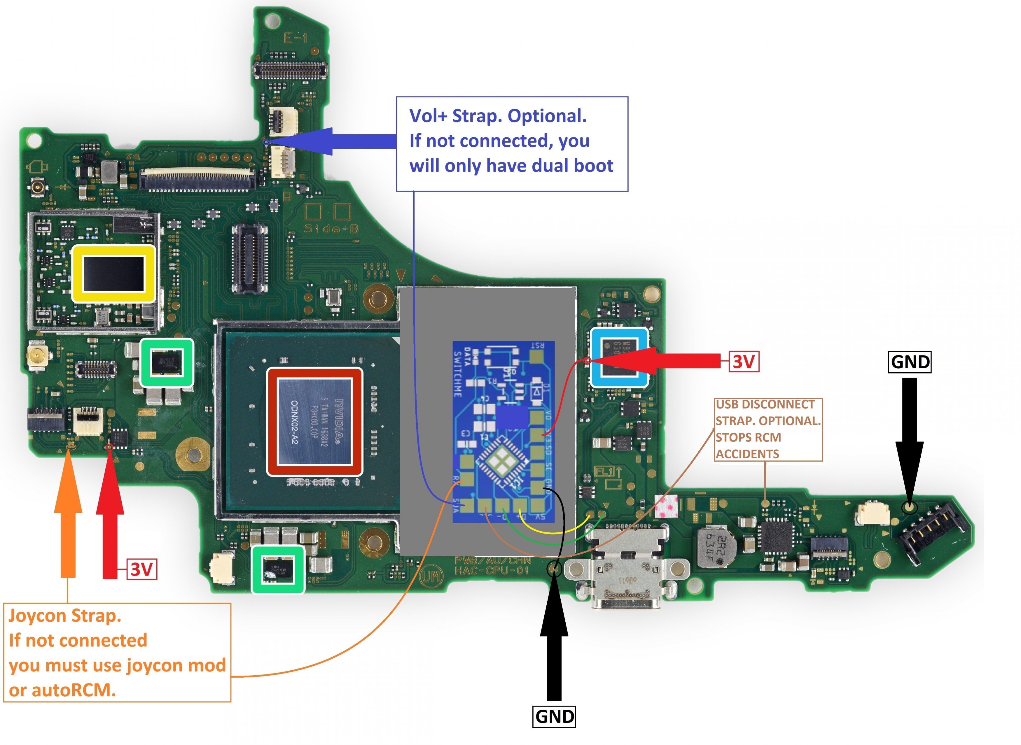
Rebug SwitchME M0. Use Trinket files.
Solder as laid out in the following picture
==================================================
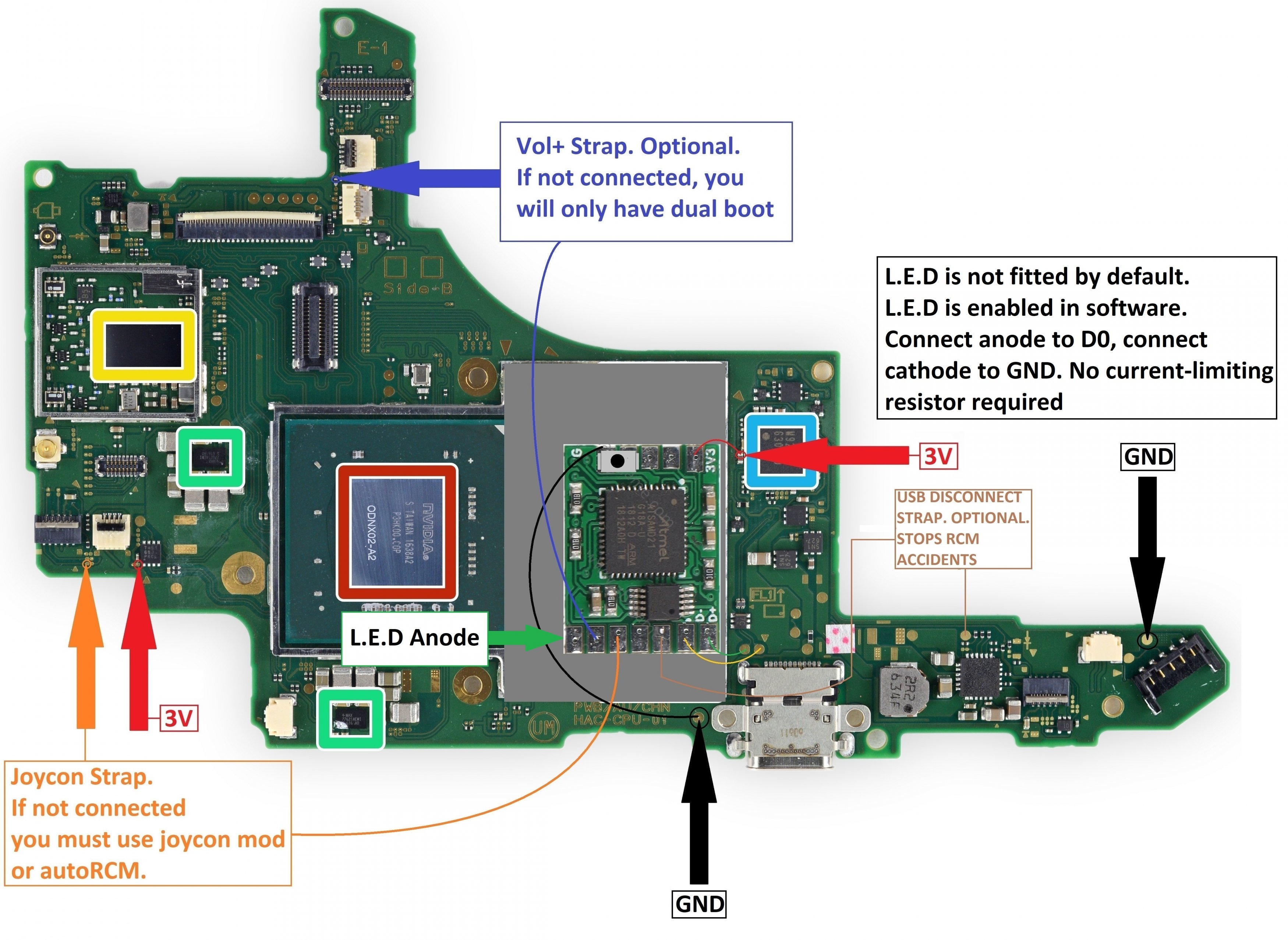
RCMX86 - Internal modchip version.
Solder as laid out in the following picture
==================================================
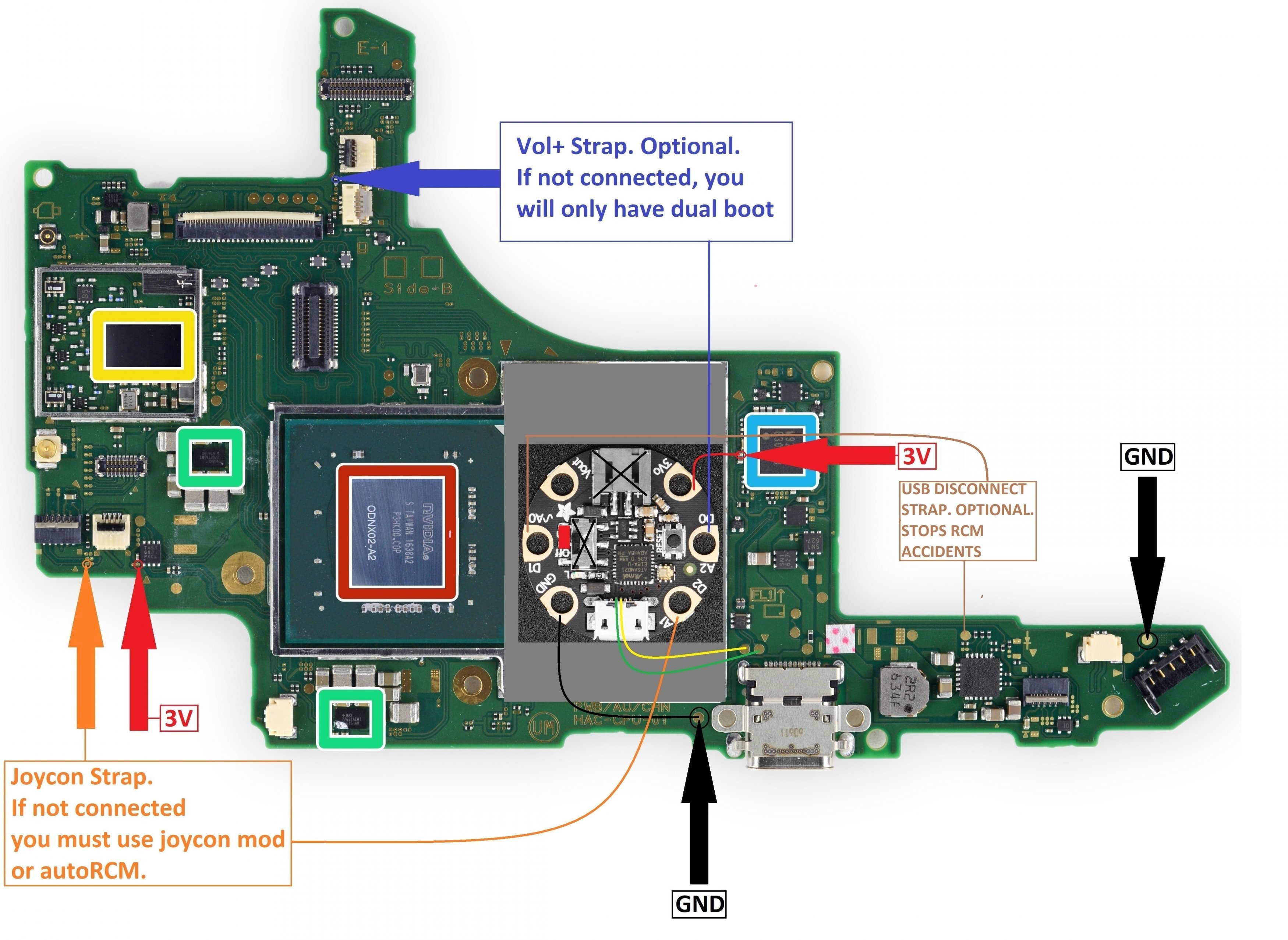
Gemma M0. Use Gemma files.
Solder as laid out in the following picture
==================================================
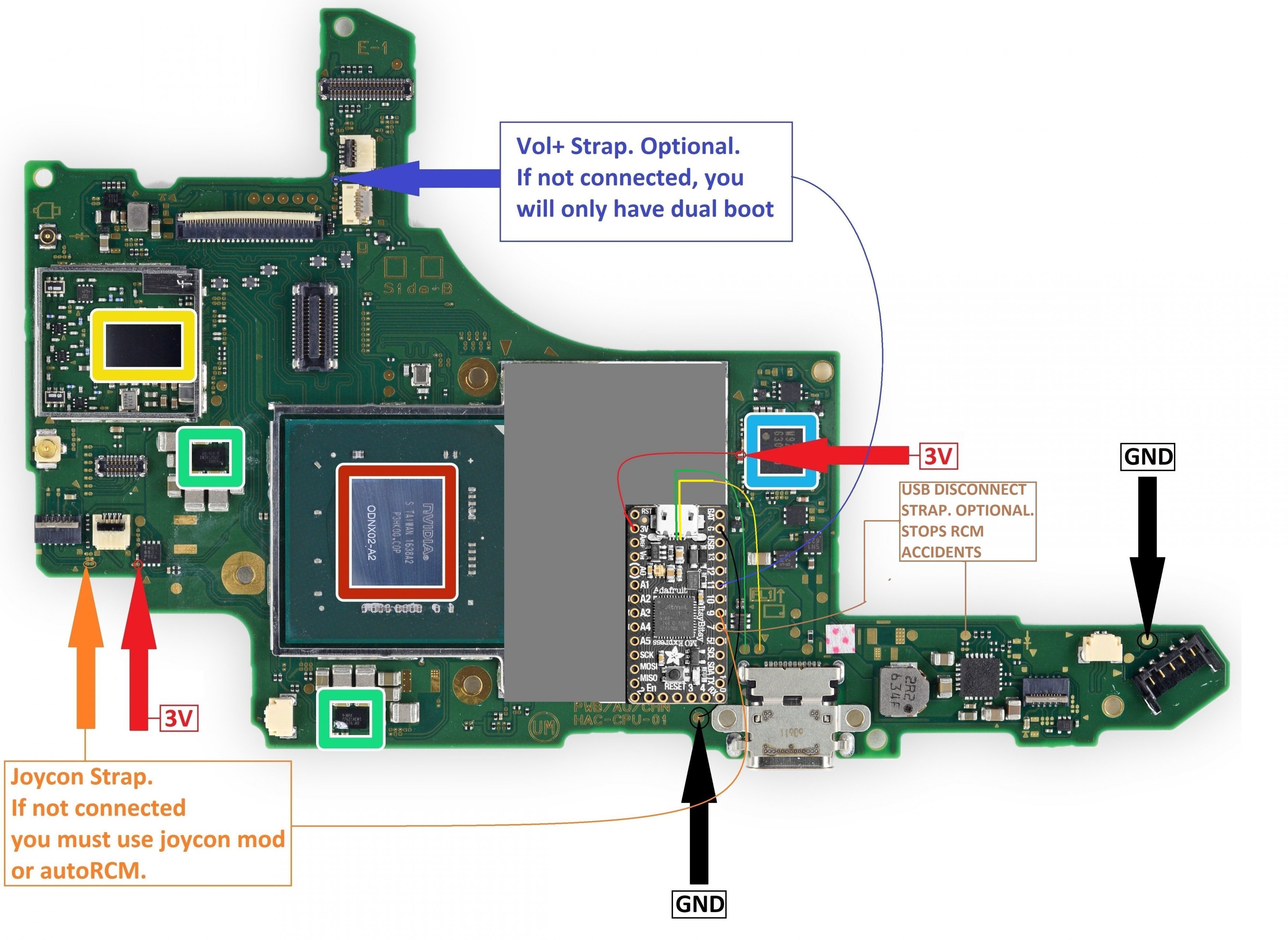
ItsyBitsy M0 Express. Use ItsyBitsy files.
Solder as laid out in the following picture
==================================================
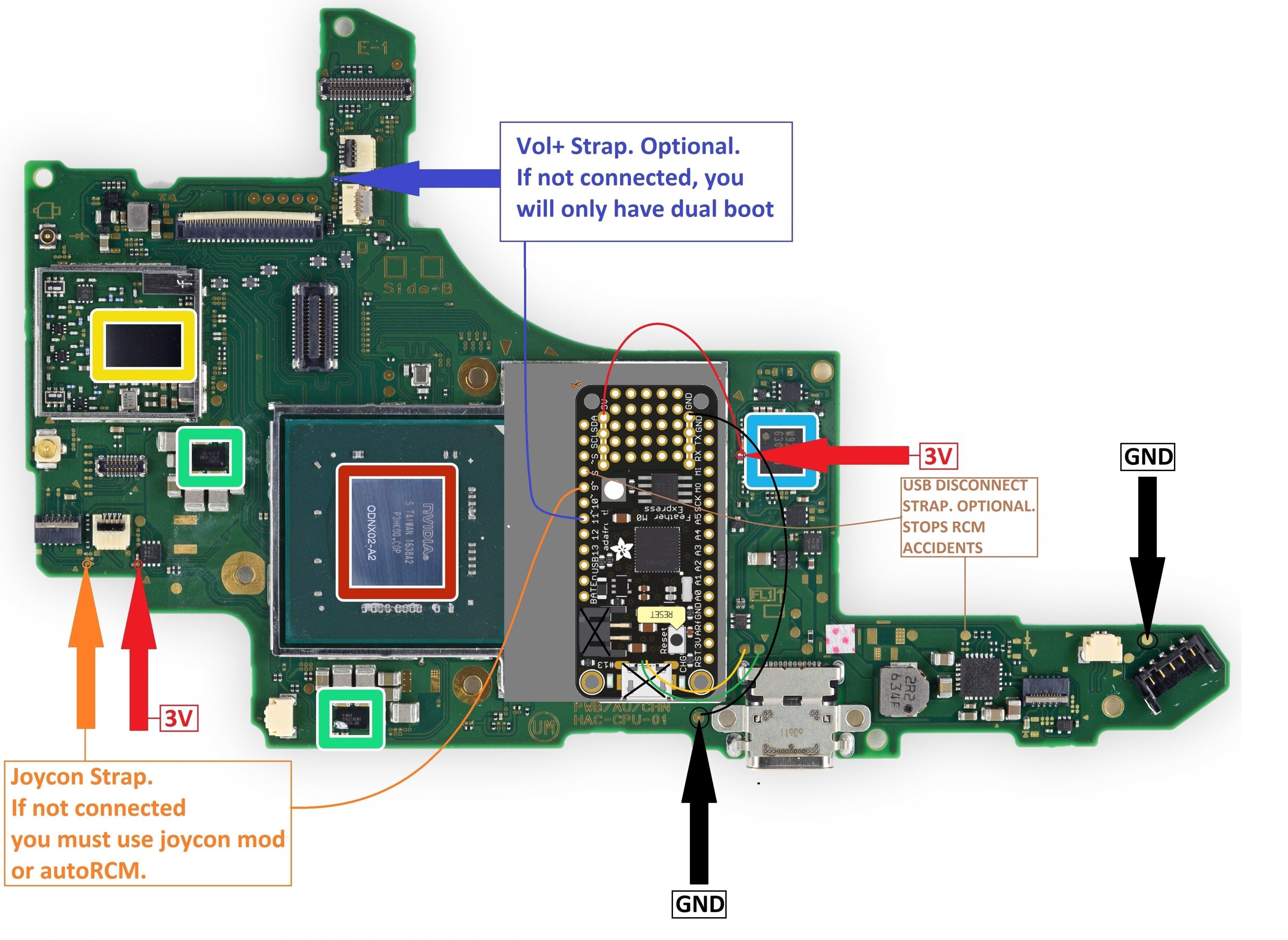
Feather M0 Express. Use Feather files.
Solder as laid out in the following picture
New Universal Method. All SAMD-based internal chips. If your chip is not supported and you cannot work it out, PM me.
Trinket M0.
Solder as laid out in the following picture
==================================================
Rebug SwitchME M0. Use Trinket files.
Solder as laid out in the following picture
==================================================
RCMX86 - Internal modchip version.
Solder as laid out in the following picture
==================================================
Gemma M0. Use Gemma files.
Solder as laid out in the following picture
==================================================
ItsyBitsy M0 Express. Use ItsyBitsy files.
Solder as laid out in the following picture
==================================================
Feather M0 Express. Use Feather files.
Solder as laid out in the following picture
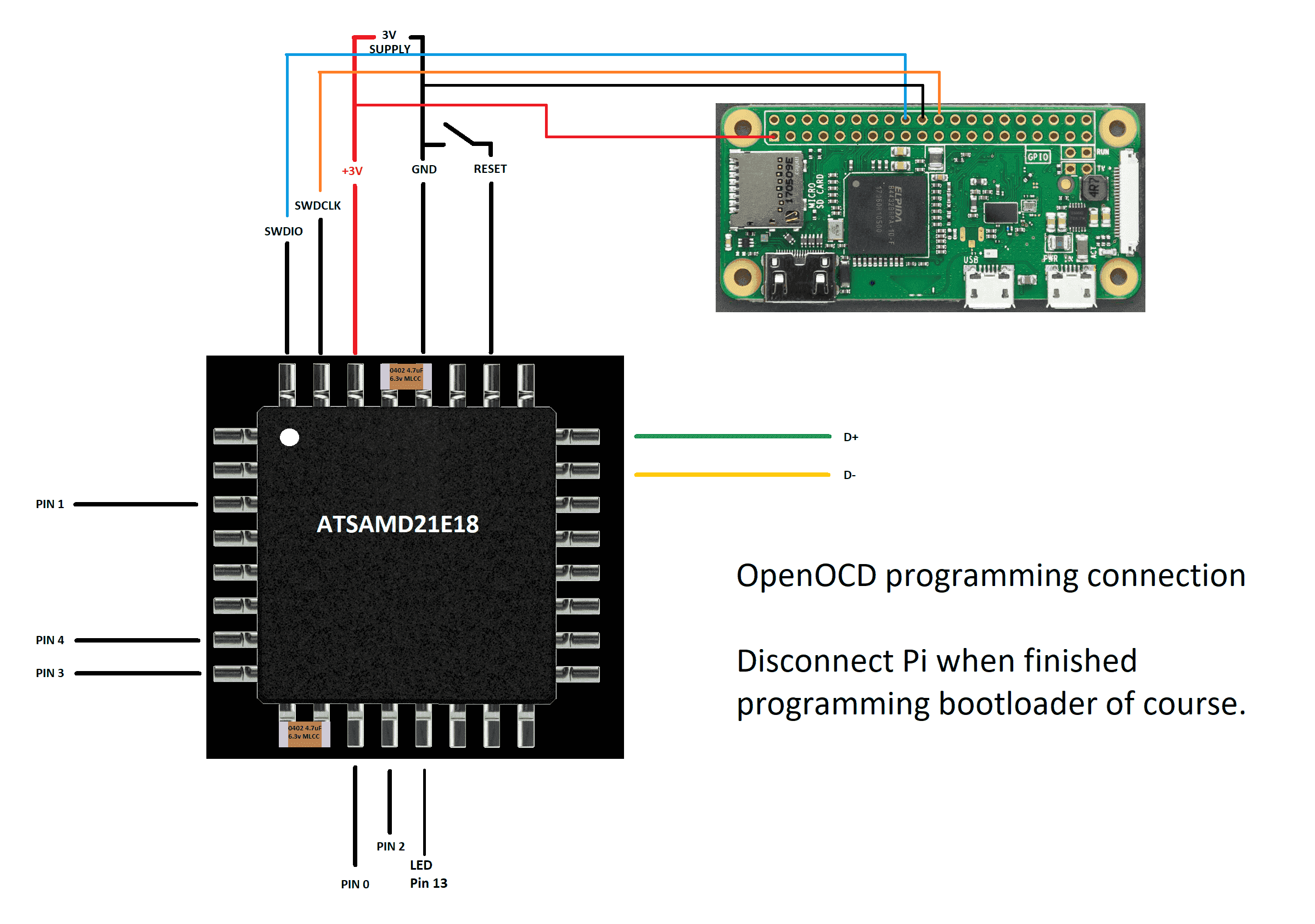
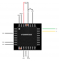
BUILD YOUR OWN FROM A QFP ATSAMD21E18. Trinket equivalent pins.
Flash Trinket bootloader using OpenOCD via serial pins SWDIO / SWDCLK. Fit a reset switch somewhere... Or going to power / wake (aka method 2). If building for external use, it is good practice to fit a third capacitor between 3V & GND. This is deliberately vague and ambigious, as this needs research and you need to know what you are doing.
Link for setting the Pi up with OpenOCD: HERE
Raspberry Pi OpenOCD image in downloads section or HERE
Flash Trinket bootloader using OpenOCD via serial pins SWDIO / SWDCLK. Fit a reset switch somewhere... Or going to power / wake (aka method 2). If building for external use, it is good practice to fit a third capacitor between 3V & GND. This is deliberately vague and ambigious, as this needs research and you need to know what you are doing.
Link for setting the Pi up with OpenOCD: HERE
Raspberry Pi OpenOCD image in downloads section or HERE
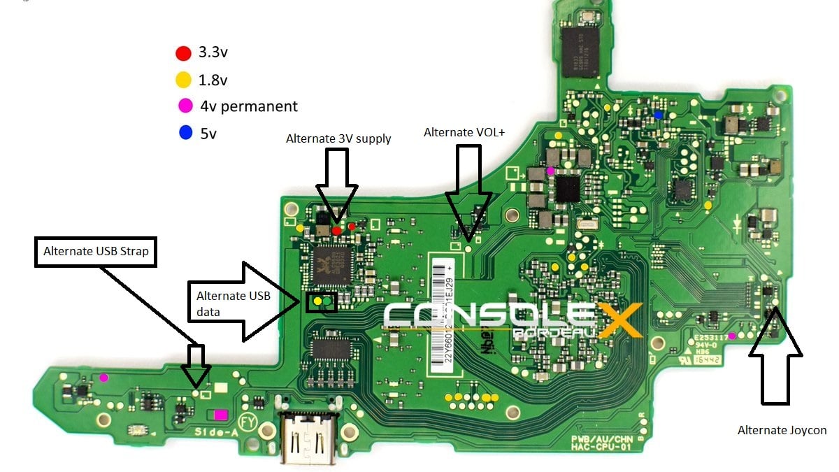
Alternative Solder Points
Credit to @consolex for original pic. I`ve added alternative points to solder to:
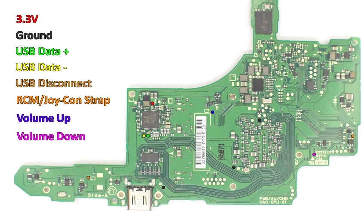
Credit to @pyorin for this much tidier version showing the same info as the above one!
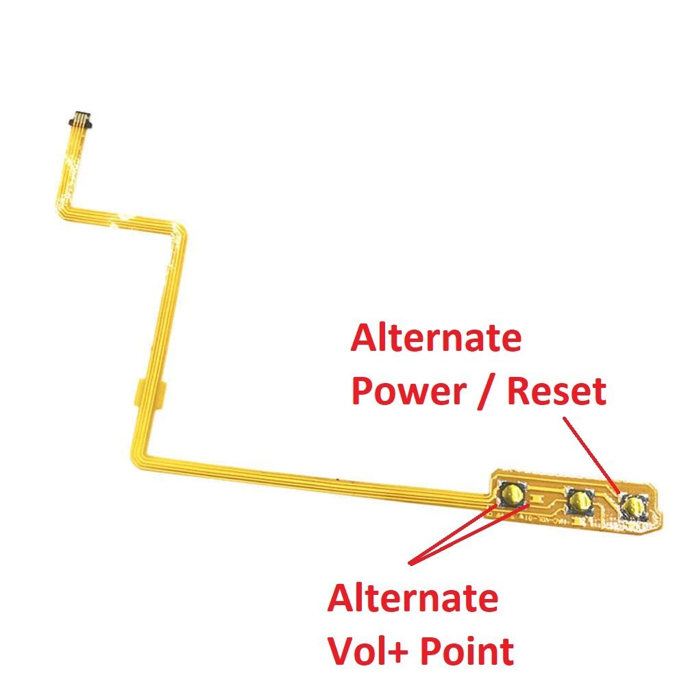
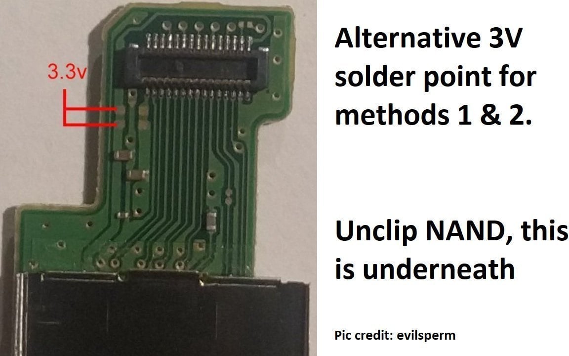
Credit to @consolex for original pic. I`ve added alternative points to solder to:
Credit to @pyorin for this much tidier version showing the same info as the above one!
Replacement Parts List
Ok... So you have damaged your switch soldering your chip in. Not to worry.
First things first, DO NOT BRIDGE THE CONTACTS HOPING TO REVIVE YOUR SWITCH. With resistors, you may possibly get away with this, but with the capacitors listed below, if you jump these points, you will make a nice short-circuit to the PMIC and / or the M92T36, killing them instantly. Don`t do it.
OK... I`ll list these parts with METHOD 2 & 3 TRINKET PIN NUMBERS and the values of the components they solder to.
TRINKET 3V (POWER SUPPLY) - 2.2uF 0402 size MLCC capacitor. Voltage unimportant as long as it is over 6.3v
TRINKET PIN 2 (POWER ON RESET - goes to pin 5 on M92T36)- 4.7uF 0402 size MLCC capacitor. Voltage unimportant as long as it is over 6.3v
TRINKET PIN 0 (VOL+) - 150R (150 ohms) 0201 Thick Film resistor. 50mW
TRINKET RESET (SWITCH POWER BUTTON) - 150R (150 ohms) 0201 Thick Film resistor. 50mW
I recommend RS components.
First things first, DO NOT BRIDGE THE CONTACTS HOPING TO REVIVE YOUR SWITCH. With resistors, you may possibly get away with this, but with the capacitors listed below, if you jump these points, you will make a nice short-circuit to the PMIC and / or the M92T36, killing them instantly. Don`t do it.
OK... I`ll list these parts with METHOD 2 & 3 TRINKET PIN NUMBERS and the values of the components they solder to.
TRINKET 3V (POWER SUPPLY) - 2.2uF 0402 size MLCC capacitor. Voltage unimportant as long as it is over 6.3v
TRINKET PIN 2 (POWER ON RESET - goes to pin 5 on M92T36)- 4.7uF 0402 size MLCC capacitor. Voltage unimportant as long as it is over 6.3v
TRINKET PIN 0 (VOL+) - 150R (150 ohms) 0201 Thick Film resistor. 50mW
TRINKET RESET (SWITCH POWER BUTTON) - 150R (150 ohms) 0201 Thick Film resistor. 50mW
I recommend RS components.
FAQ
Q - How do I boot the switch into APX (RCM) mode?
A - You need to short out pin 10 on the right joycon rail to GND with a jig or modded joycon or paperclip (not recommended... Buy a jig you cheap-ass gyppo). Once shorted out, hold down vol+ and power. The switch screen should be off... Plug into your PC and it should recognise a APX device. Well done. You are in RCM.
Q - What glue should I use?
A - Only glue if necessary! Ideally if your soldering is of sufficient quality and your wire is thin enough, you don`t need glue. I use a bit because I am OCD. Anyway, use Epoxy. It`s what I use. Gives you some working time, is solid. Superglue makes a mess DO NOT USE SUPERGLUE. The only thing super about it is how it melts things. Epoxy won`t stick to the shield long-term, so bear that in mind. Pure Acetone will remove epoxy. Acetone tends to remove / melt anything to be warned. CHECK YOUR GLUE WON`T GO CONDUCTIVE OVER TIME - LOOKING AT YOU SCAMSUNG! The combination of heat cycles and absorbing of moisture can turn adhesive into a high-impedance connection!
Q - What size wire should I use?
A - I use AWG40 magnet wire or AWG30 Kynar. AWG40 goes onto components easier... And if you snap it, chances are the wire will snap and not the trace / component.
A2 - You can also use AWG30. I recommend Kynar wrapping wire but any will do. Looks nice, good resistance to elements, tidy. Nothing thicker than AWG30. You are just causing yourself more headaches. Trust me.
Q - Is AWG40 thick enough?
A - Yes. AWG40 is good for around 90mA.
Q - which methods do you recommend?
A - Connect all the straps...
Q - how do you recommend to set it up?
A - Fusee Suite. Search for Fusee Suite or go to link at top of this OP.
Q - My switch is flat and won't turn on.
A - Have you got the charger connected? Disconnect it or your switch won't boot! Boot to a payload (SX loader/Hekate), reconnect charger and leave on the payload menu and charge. Leave for 15 minutes and switch will start normally. It will continue charging one booted.
IF YOU REQUIRE SUPPORT, IF YOUR CONSOLE ISN`T WORKING CORRECTLY... PLEASE POST A HIGH RESOLUTION PICTURE OF YOUR INSTALL. You might think it isn`t your soldering, but in all cases with the new methods, it is bad soldering. So, please post a picture.
A BRIEF WARNING - PLEASE READ
Q - How do I boot the switch into APX (RCM) mode?
A - You need to short out pin 10 on the right joycon rail to GND with a jig or modded joycon or paperclip (not recommended... Buy a jig you cheap-ass gyppo). Once shorted out, hold down vol+ and power. The switch screen should be off... Plug into your PC and it should recognise a APX device. Well done. You are in RCM.
Q - What glue should I use?
A - Only glue if necessary! Ideally if your soldering is of sufficient quality and your wire is thin enough, you don`t need glue. I use a bit because I am OCD. Anyway, use Epoxy. It`s what I use. Gives you some working time, is solid. Superglue makes a mess DO NOT USE SUPERGLUE. The only thing super about it is how it melts things. Epoxy won`t stick to the shield long-term, so bear that in mind. Pure Acetone will remove epoxy. Acetone tends to remove / melt anything to be warned. CHECK YOUR GLUE WON`T GO CONDUCTIVE OVER TIME - LOOKING AT YOU SCAMSUNG! The combination of heat cycles and absorbing of moisture can turn adhesive into a high-impedance connection!
Q - What size wire should I use?
A - I use AWG40 magnet wire or AWG30 Kynar. AWG40 goes onto components easier... And if you snap it, chances are the wire will snap and not the trace / component.
A2 - You can also use AWG30. I recommend Kynar wrapping wire but any will do. Looks nice, good resistance to elements, tidy. Nothing thicker than AWG30. You are just causing yourself more headaches. Trust me.
Q - Is AWG40 thick enough?
A - Yes. AWG40 is good for around 90mA.
Q - which methods do you recommend?
A - Connect all the straps...
Q - how do you recommend to set it up?
A - Fusee Suite. Search for Fusee Suite or go to link at top of this OP.
Q - My switch is flat and won't turn on.
A - Have you got the charger connected? Disconnect it or your switch won't boot! Boot to a payload (SX loader/Hekate), reconnect charger and leave on the payload menu and charge. Leave for 15 minutes and switch will start normally. It will continue charging one booted.
Disclaimer:
You have only yourself to blame. This voids warranty. This may or may not get you banned from online services. If it does, you got yourself banned. I`m not responsible if you kill your switch / your first-born with any of this in this post. I`m not infalliable. I`m partly senile. Do your own research. Kids, get bill payers permission before you attempt even using a screwdriver.
NUTSHELL: Don`t come having a go at me because you fooked your £300 console up. I`ll do my best to help you though if you do, Just don`t blame me.
You have only yourself to blame. This voids warranty. This may or may not get you banned from online services. If it does, you got yourself banned. I`m not responsible if you kill your switch / your first-born with any of this in this post. I`m not infalliable. I`m partly senile. Do your own research. Kids, get bill payers permission before you attempt even using a screwdriver.
NUTSHELL: Don`t come having a go at me because you fooked your £300 console up. I`ll do my best to help you though if you do, Just don`t blame me.
Credits to Quantum-Cross, Atlas44, @Ninoh-FOX , @jcrorxp , @tecfreak, @mooglazer, @subcon959, @64Dp128k, @mikeleuskaldunak, @M-O-B, CTCaer, @evilsperm, @consolex and everyone else for valuable input.
IF YOU REQUIRE SUPPORT, IF YOUR CONSOLE ISN`T WORKING CORRECTLY... PLEASE POST A HIGH RESOLUTION PICTURE OF YOUR INSTALL. You might think it isn`t your soldering, but in all cases with the new methods, it is bad soldering. So, please post a picture.
A BRIEF WARNING - PLEASE READ
THIS MOD IS NOT FOR THE FEINT OF HEART. WE ARE SOLDERING TO TRACES AND COMPONENTS ON THE FRONT SIDE OF THE BOARD TO SAVE HAVING TO REMOVE THE BOARD AND SOLDER TO TESTPOINTS. IF YOU ARE STRUGGLING, OR THINK YOU ARE GOING TO STRUGGLE, PLEASE PLEASE SOLDER TO THE TEST POINTS NOTED IN THIS AND OTHER THREADS (YOU WILL NEED TO REMOVE THE MOTHERBOARD). DOUBLE - TRIPLE CHECK EVERYTHING. YOU HAVE BEEN WARNED!!!
Good soldering skills are needed!
A magnifying glass is needed!
Good soldering iron needed - ideally with a 0.3 conical tip. No more than 30w!
SECURE YOUR WIRES PRIOR TO SOLDERING. Stick them down with double-sided tape.
Only use glue if you need to and glue wires after soldering. Don`t glue the solder to the component!
Put the tiniest amount of glue on the PCB mask only. Never on components. Use a cocktail stick for more glue control!!!
Take a look at alternative solder points to get you out of the sh*t if you do rip something off the board
If you aren`t the best at soldering, then think very carefully about connecting to pin 6 capacitor (the one in these new methods). If you rip this pad, you WILL NEED TO REMOVE YOUR BOARD and run from a testpoint.
Good soldering skills are needed!
A magnifying glass is needed!
Good soldering iron needed - ideally with a 0.3 conical tip. No more than 30w!
SECURE YOUR WIRES PRIOR TO SOLDERING. Stick them down with double-sided tape.
Only use glue if you need to and glue wires after soldering. Don`t glue the solder to the component!
Put the tiniest amount of glue on the PCB mask only. Never on components. Use a cocktail stick for more glue control!!!
Take a look at alternative solder points to get you out of the sh*t if you do rip something off the board
If you aren`t the best at soldering, then think very carefully about connecting to pin 6 capacitor (the one in these new methods). If you rip this pad, you WILL NEED TO REMOVE YOUR BOARD and run from a testpoint.
Attachments
Last edited by mattytrog,