Hacking Hardware Misc Tutorial
Updated
Switch Oled 8000mAh(80% MORE PLAYTIME) Battery Mod(Showcase/Guide) [Part 1]
To celebrate the reveal of the Switch 2, I decided to finally pick up the soldering iron and finish a project I have been working on for years; doubling the Switch's battery life.
WARNING: Attempting this mod without requisite knowledge or research may result in FIRE, EXPLOSION OR WORSE!
Before I continue the post, let me show proof that my switch has 8000mAh of capacity now.

Now that that's out of the way, let me talk about the more interesting part, journey to achieve a near doubling of battery capacity for the switch. Over a year ago, I posted my first viable battery mod. If you want the remaining portion of my guide to make sense, you should probably read that post. At the time, I knew more was possible and set out to improve the capacity of the switch even further. I did more research and bought everything I thought I would need. However, a failed modchip install and life kinda got in the way. I also thought that more people on the western net would try their hands at a battery mod and evolve the methods in the guide I wrote. However, apart from one bodged implementation by a Youtuber, nothing materialized. So after getting some more equipment to salvage my OLED and finally install a modchip, I have a improved battery mod up and running.
Step 1: Cell Selection & Testing
I won't be going through the details of what makes a good cell and how to test batteries you find online this time, read my previous guide for that.
Instead, this time I'll be outlining some potential candidates and what I chose. Battery bay max size has been expanded to 72(w)x77(l)x9.5?~(h)mm this time with some internal physical "alterations" I made this time.
At the time I started this mod, the only real viable options to construct a 9.5mm~ battery was LTF26A+BA091F(9100mAh). However in 2025, due to a wave of Chinese smartphones hitting the market with silicon anode batteries, we can construct a 10000mAh(LTF26A+BA72) battery. Once this technology becomes more commonplace and more viable cells arrive, expect my 8000mAh mod to look underwhelming.
I did a initial test of the cells I used for the mod and got a potential real capacity of 7565mAh.

That seemed satisfactory to me at the time, so I continued.
Step 2: Creating a Modded Battery pack for the Switch.
The same principles as my previous guide apply. I chose to use the Switch's original Battery protection circuit instead of bypassing it and using my own this time. This will bite me in the ass later in the guide which is why this thing needs a Part 2. I don't have any pictures of the assembly this time, so you'll have to use your imagination for now.
Step 3: Modifications to the Switch Frame
This was the step I skipped out on last time. This adds over a 1mm to the battery bay thickness and accounts for 1000mAh out of the 1600mAh increase over last time.
First up, strip the Switch's metal midframe of everything except maybe the speakers:
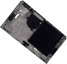
You can buy these things online, so do that if you want a backup or to revert the mod.
Next, knock out all the metal in the battery compartment. I used a hammer and pliers for this. Probably not the best tools since I caused a crack that spread outside of the the battery compartment. A dremel with a cutting disc is probably more appropriate.


This is just a rough cut, you need to sand/grind down the edges. I used a knockoff dremel with a cutting disk and sanding disk.

Remember to clean the midframe and workspace of metal dust unless a shorted motherboard repair seems particularly fun and cheap.
Step 4: Make it Fit
Reassemble your switch up to this point:


Now, we need to mount the battery to the sidewalls of the compartment now since bonding it directly to the screen is a idea and removing it will inccurs a high change of damaging the screen. I used foam and VHB tape to give my battery some wiggle room to expand.

Now you might have also noticed, the EMI shield needs trimming to fit. Trim EMI shield & anntenae(if needed) accordingly and appropiately to fit the battery. Trim off only black plastic of anntenae.
Step 5: Enjoy!
After reassembling the switch, discharge and recharge the battery 100-0, 0-100. By 0%, I mean 0%. Make sure the switch switch turns off with the red battery warning. Recharge till charging current is 0mA to ensure battery is fully charged.
You should probably do some experiments to make sure your battery isn't a dud. I ran this scene and setup for 15w power draw in P5R. It held steady for 10minutes. The stock battery would 100% brownout here.

If you followed my steps 100% up to this point you would have noticed the capacity got was most likely around 7400mAh, well, there is one more step I took..
Bonus Step: Modifications to Hekate to Force Charging to 4.4v
By default, non-lite switches charge to 4.2v. This means on our 4.4v, 4.5v smartphone cells we are losing as much as 10-15% of the rated capacity. The switch's bq24193 is 100% capable of charging to 4.4v though, we just need to send the right commands to this IC.
I downloaded the hekate source code and poked around and found how to force any max charge voltage. Now I am a terrible coder and know basically no C++, so what I did is probably extremely inadvisible, but it did work.
I made the following in changes in bq24193.c:
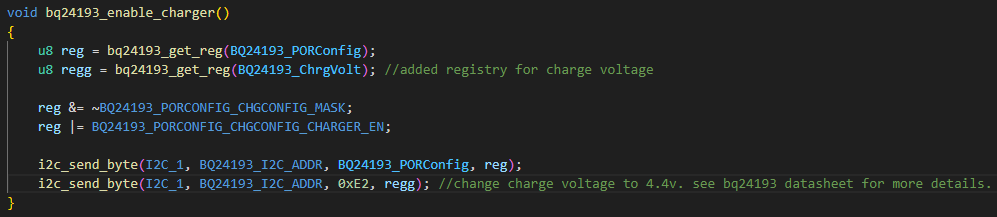
Booting into Hekate now shows us 4400mV charge voltage instead of 4208mV. Great! But...
Life is never that easy.
First of all, my decision to use the switch battery protection board means any voltage above 4.3v reaching the battery causes over-charge protection to kick in. Bummer. But not a dealbreaker at all. Setting charge voltage to 4288mV fixes this for now and gives us 8000mAh of capacity. And it's easily fixable with a board meant for 3.85v cells and some craftsmanship.
The real problem is that the moment HOS is booted, the bq24193 is set back to 4.208v. In theory, homebrew could be written to set it back immediately after boot. On the switchbrew website it seems the powctl service can be used to change charge voltage in HOS easily. Fantastic!
...Except for the fact it's not present on retail units.
Ok, no problem, I'll do it the hard way and use bus services instead and set the charge voltage by communicating with the charge controller via I2C.
But, as we have established earlier, I don't know how to make Switch Homebrew or write C++. This is way above my pay grade.
So for now, I have to charge with the switch powered off after booting hekate. Sucks to suck, I guess.
If anyone reading this knows how to do write what I want to do, please help me, or there probably won't be a part 2 with a 9000mAh+ battery
WARNING: Attempting this mod without requisite knowledge or research may result in FIRE, EXPLOSION OR WORSE!
Before I continue the post, let me show proof that my switch has 8000mAh of capacity now.
Now that that's out of the way, let me talk about the more interesting part, journey to achieve a near doubling of battery capacity for the switch. Over a year ago, I posted my first viable battery mod. If you want the remaining portion of my guide to make sense, you should probably read that post. At the time, I knew more was possible and set out to improve the capacity of the switch even further. I did more research and bought everything I thought I would need. However, a failed modchip install and life kinda got in the way. I also thought that more people on the western net would try their hands at a battery mod and evolve the methods in the guide I wrote. However, apart from one bodged implementation by a Youtuber, nothing materialized. So after getting some more equipment to salvage my OLED and finally install a modchip, I have a improved battery mod up and running.
Step 1: Cell Selection & Testing
I won't be going through the details of what makes a good cell and how to test batteries you find online this time, read my previous guide for that.
Instead, this time I'll be outlining some potential candidates and what I chose. Battery bay max size has been expanded to 72(w)x77(l)x9.5?~(h)mm this time with some internal physical "alterations" I made this time.
| Cell/Battery Origin and Name | Capacity(mAh), Voltage(V) | Dimensions(HHWWLL) | Remarks |
| LeEco LePro 3 AI Edition, LTF26A | 4000, 3.85 | 436876 | The original cells used in my old post. Most of the ones on the market are >5years old, but I haven't found a suitable replacement for a 4mm thick cell. |
| Meizu 17(Pro) 3rd Party High-Capacity Cell, BA091F? | 5100, 3.87 | 516874 | The best 5mm cell I found when I first began a year ago. Still the easiest to find and cheapest of the 5mm cells. Has a 4500mAh capacity when charged to 4.2v. |
| Meizu 15 Plus, BA891 | 3500, 3.85 | 386878 | A useful option if the other cell used is too thick with the LTF26A. Suffers from the same issue as the LTF26A to a lesser extent. |
| Huawei Pura 70 Ultra, HB536979 | 5200, 3.91 | 536979 | The cell that has maximum utilization of the switch's battery bay area. Difficult to source and without standout characteristics to compensate. |
| Vivo X200 Pro, BA72 | 6000, 3.84 | 546776 | The best 5mm~ cell in early 2025. Has chart topping power density and capacity due to use of lithium-silicon chemistry. Possible to source on Chinese 2nd-hand markets for a high price due to demand from DIY cell phone battery capacity upgrades. |
At the time I started this mod, the only real viable options to construct a 9.5mm~ battery was LTF26A+BA091F(9100mAh). However in 2025, due to a wave of Chinese smartphones hitting the market with silicon anode batteries, we can construct a 10000mAh(LTF26A+BA72) battery. Once this technology becomes more commonplace and more viable cells arrive, expect my 8000mAh mod to look underwhelming.
I did a initial test of the cells I used for the mod and got a potential real capacity of 7565mAh.
That seemed satisfactory to me at the time, so I continued.
Step 2: Creating a Modded Battery pack for the Switch.
The same principles as my previous guide apply. I chose to use the Switch's original Battery protection circuit instead of bypassing it and using my own this time. This will bite me in the ass later in the guide which is why this thing needs a Part 2. I don't have any pictures of the assembly this time, so you'll have to use your imagination for now.
Step 3: Modifications to the Switch Frame
This was the step I skipped out on last time. This adds over a 1mm to the battery bay thickness and accounts for 1000mAh out of the 1600mAh increase over last time.
First up, strip the Switch's metal midframe of everything except maybe the speakers:
You can buy these things online, so do that if you want a backup or to revert the mod.
Next, knock out all the metal in the battery compartment. I used a hammer and pliers for this. Probably not the best tools since I caused a crack that spread outside of the the battery compartment. A dremel with a cutting disc is probably more appropriate.
This is just a rough cut, you need to sand/grind down the edges. I used a knockoff dremel with a cutting disk and sanding disk.
Remember to clean the midframe and workspace of metal dust unless a shorted motherboard repair seems particularly fun and cheap.
Step 4: Make it Fit
Reassemble your switch up to this point:
Now, we need to mount the battery to the sidewalls of the compartment now since bonding it directly to the screen is a idea and removing it will inccurs a high change of damaging the screen. I used foam and VHB tape to give my battery some wiggle room to expand.
Now you might have also noticed, the EMI shield needs trimming to fit. Trim EMI shield & anntenae(if needed) accordingly and appropiately to fit the battery. Trim off only black plastic of anntenae.
Step 5: Enjoy!
After reassembling the switch, discharge and recharge the battery 100-0, 0-100. By 0%, I mean 0%. Make sure the switch switch turns off with the red battery warning. Recharge till charging current is 0mA to ensure battery is fully charged.
You should probably do some experiments to make sure your battery isn't a dud. I ran this scene and setup for 15w power draw in P5R. It held steady for 10minutes. The stock battery would 100% brownout here.
If you followed my steps 100% up to this point you would have noticed the capacity got was most likely around 7400mAh, well, there is one more step I took..
Bonus Step: Modifications to Hekate to Force Charging to 4.4v
By default, non-lite switches charge to 4.2v. This means on our 4.4v, 4.5v smartphone cells we are losing as much as 10-15% of the rated capacity. The switch's bq24193 is 100% capable of charging to 4.4v though, we just need to send the right commands to this IC.
I downloaded the hekate source code and poked around and found how to force any max charge voltage. Now I am a terrible coder and know basically no C++, so what I did is probably extremely inadvisible, but it did work.
I made the following in changes in bq24193.c:
Booting into Hekate now shows us 4400mV charge voltage instead of 4208mV. Great! But...
Life is never that easy.
First of all, my decision to use the switch battery protection board means any voltage above 4.3v reaching the battery causes over-charge protection to kick in. Bummer. But not a dealbreaker at all. Setting charge voltage to 4288mV fixes this for now and gives us 8000mAh of capacity. And it's easily fixable with a board meant for 3.85v cells and some craftsmanship.
The real problem is that the moment HOS is booted, the bq24193 is set back to 4.208v. In theory, homebrew could be written to set it back immediately after boot. On the switchbrew website it seems the powctl service can be used to change charge voltage in HOS easily. Fantastic!
...Except for the fact it's not present on retail units.
Ok, no problem, I'll do it the hard way and use bus services instead and set the charge voltage by communicating with the charge controller via I2C.
But, as we have established earlier, I don't know how to make Switch Homebrew or write C++. This is way above my pay grade.
So for now, I have to charge with the switch powered off after booting hekate. Sucks to suck, I guess.
If anyone reading this knows how to do write what I want to do, please help me, or there probably won't be a part 2 with a 9000mAh+ battery
Attachments

Last edited by DaLZy,