
Help installing Hwfly v4 on Erista Patched

  • Thread starter Thread starter zakwarrior
  • Start date Start date
  • Views Views 11,977
  • Replies Replies 9

zakwarrior

Well-Known Member
Newcomer
Joined
Feb 20, 2016
Messages
60
Reaction score
30
Trophies
0
Age
42
XP
303
Country
France
Hi everyone,

I'm having some isues with this new hwfly v4, it works fine on oled but it said that it should also work on mariko, lite or erista patched

I'm trying to make it work on erista patched, the problem is i didn't find any diagram for this (only for mariko), so i decided to test and do everything myself from scratch

So the main problem is that on erista patched you cannot use the provided CPU QSB as the caps are not in the same position, si i used a v1 cable and wired everything up

I tried 2 different setups (since i'm not sure...) and made my own diagrams to show you guys how it was wired

here is first setup and as result i get a slow blinking orange that will never stop blinking (EVEN after turn off after the orange blink, she won't go purple):
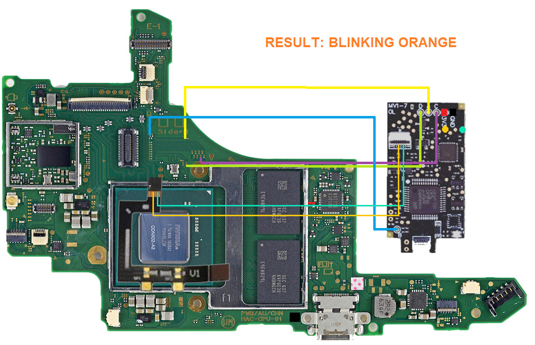
setup_blinking-orange.jpg


And here is my second setup and as result i get a solid red light :
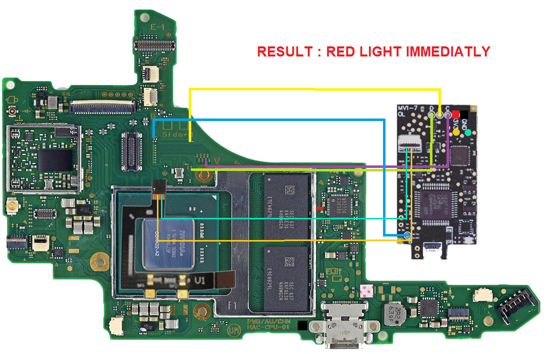
setup_red-light.jpg


Anyone know what is the issue ?

P.S: I tried to flash also the modchip with spacecraft v1, with the first setup it blinks yellow, if i turn off then back on it blinks purple 3 or 4 times then freeze on purple light

P.S.2: the modchip was not flasher with hwfly toolbox since i hear the last firmware had strange bugs
Thanks for the help

 
Maybe the ribbon cable pinout is different? This diagram is for F2v1-6 ribbon for erista. Pin 3-4 are used to drive mosfet and pin 2 is voltage sense pin. The modchip seller mentioned to me different ribbon cables come with different chips aren't cross compatible. Maybe trace the connection on your pcb to make sure. Also the GD32 microcontroller has 2 voltage sense pins (MARIKO_ADC and ERISTA_ADC), I think you should use ERISTA_ADC for patched v1.
1659832282908.png
 
  • Like
Reactions: x3n0
Maybe the ribbon cable pinout is different? This diagram is for F2v1-6 ribbon for erista. Pin 3-4 are used to drive mosfet and pin 2 is voltage sense pin. The modchip seller mentioned to me different ribbon cables come with different chips aren't cross compatible. Maybe trace the connection on your pcb to make sure. Also the GD32 microcontroller has 2 voltage sense pins (MARIKO_ADC and ERISTA_ADC), I think you should use ERISTA_ADC for patched v1.
View attachment 321544
thanks for the diagram, it will help a lot, i think i switched the pins.... Instad of using pin 2 and 3/4, looks like i used pin 3 & 5....

I started from right to left 123456 because i thought it had to be inversed...

I will test tomorow and let you know

Thanks
 
thanks for the diagram, it will help a lot, i think i switched the pins.... Instad of using pin 2 and 3/4, looks like i used pin 3 & 5....

I started from right to left 123456 because i thought it had to be inversed...

I will test tomorow and let you know

Thanks
Good friend, did you manage to solve the problem?, what scheme did you use, could you put a photo or scheme? I'm in the same situation with a v1 and I can't get it to work with an oled chip. Thank you very much.
 
Hey there

First thanks to x3no and Randy for those hints it helped me ;)

Yeah now it works, x3no was right, i had to connect the other pins.... Just know one thing VERY important, if you have tried wiring it and tested different ways, you probably burned the switch, i understood this after making everything right and the chip was blinking purple and green light was static and nothing on screen

I did everything back with another erista that was working correctly and everything went fine

Just imagine the qsb of v1 going into the chips with the pins facing up
The mistake was not connecting mariko ADC to ground, because when you use v1 qsb it puts mariko adc pin to ground, when you use Ev2 qsb it puts erista adc pin to ground, using diagram 1 where it was blinking orange but this will only work with the original firmware on the chip v4! don't put any other firmware as this chips is wired differently then others

If you change to spacecraft or hwfly toolbox you need to re-wire correctly the chip by putting Mariko ADC to ground, take out the 10k resistor from the chip that connects erista ADC to ground, connect Erista ADC from GD32 to Erista ADC from QSB (green line), orange line is good and then it will work with the other firmwares


Voilà hope this helps
 
Last edited by zakwarrior,
Hello, is it possible to create a more detailed
Hey there

First thanks to x3no and Randy for those hints it helped me ;)

Yeah now it works, x3no was right, i had to connect the other pins.... Just know one thing VERY important, if you have tried wiring it and tested different ways, you probably burned the switch, i understood this after making everything right and the chip was blinking purple and green light was static and nothing on screen

I did everything back with another erista that was working correctly and everything went fine

Just imagine the qsb of v1 going into the chips with the pins facing up
The mistake was not connecting mariko ADC to ground, because when you use v1 qsb it puts mariko adc pin to ground, when you use Ev2 qsb it puts erista adc pin to ground, using diagram 1 where it was blinking orange but this will only work with the original firmware on the chip v4! don't put any other firmware as this chips is wired differently then others

If you change to spacecraft or hwfly toolbox you need to re-wire correctly the chip by putting Mariko ADC to ground, take out the 10k resistor from the chip that connects erista ADC to ground, connect Erista ADC from GD32 to Erista ADC from QSB (green line), orange line is good and then it will work with the other firmwares


Voilà hope this helps

Thanks for the info, I've been trying to understand for a few hours what is being stated as I'm trying to use the HwFly v4 for a patched Erista as well. I tried looking up a data sheet for the GD32F350 48 pin chip but many pins are ADC. Which pin is ERISTA_ADC and MARIKO ADC?

I tried to figure those pins out by looking for the 10kohm resistor on the chip. I found two one is pin 12 and the other is pin 41. Resistance measures were taken on the board (not off). But then when QSB v1 is connected to the chip directly is by default connected to ground? Then what is the mistake?

Just really confused here. Did you end up using the v2 flex or the v1 flex? So by putting Mariko ADC to ground it tells the chip that ERISTA is connected? And if ERISTA ADC is connected to ground it tells the chip that MARIKO is connected?

Some clarity would be much appreciate. Just don't want to fry a Switch.
 

Site & Scene News