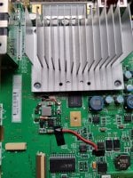
Seems you are pretty advanced at electronics repair
sure, i am botfixer

Ok, didn't think that anyone would really care, but ok, let's go:
Tutorial Wii repair
Some time ago I wanted to use my Wii again. I discovered that it no longer worked. At first I thought there was only one broken cable, but I couldn't get it to work anymore. Well, you could say that a Wii doesn't cost anything these days and you could just buy a new one. But I think that's a shame because there are many years of history on this device, as well as scores and games that have been bought. Unfortunately, I did not have a current NAND backup and reading out by unsoldering the NAND or reading out in-place with Infector or something like that should not lead to the desired result according to some information in the forum. It also seems difficult to get the tools to do this.
I'm also an electronics technician and I didn't want to put up with it. So I took a closer look at the thing. The following symptoms were shown:
- If the Wii is plugged into the power supply, the red LED comes on as usual
- You can turn on the Wii so that the LED turns green and the blue Drive LED flashes once
- The TV shows "no signal"
- You can insert and eject DVD
- You can turn off the Wii again by holding down the power button for a longer period of time
- You can switch on the Wii with the WiiMote
- Pressing the reset button at the same time when switching on does not lead to anything.
I then completely disassembled the Wii so that I can test the Bluetooth and Wifi module. I also ordered a working Wii from ebay. But even swapping the modules did not bring any improvement.
Unfortunately there are no circuit diagrams for the Wii, so you are on your own. There is a "Compendium" on BitBuild. Although this is not a schematic, it is a reverse of the circuit board in all of its layers. You can see very well where which conductor paths go. That helps. The guys at BitBuild seem to have a lot of know-how, but they don't seem to be interested in Wii repairs, just building portable Wiis. To do this, cut up Wii circuit boards and rewire them so that they fit into a small housing. There they give a lot of information about the internal voltage generation in the Wii.
A guy named Shank gives a lot of useful information here:
http://forums.modretro.com/index.php?threads/wii-board-revisions-guide.14059/
https://bitbuilt.net/forums/index.php?threads/wii-motherboard-anatomy-101.1286/
I was able to check whether my Wii still had the necessary voltages (1, 1.15, 3.3 and 5 volts). This can be measured at the connections of the coils (as shown in the thread on the picture). This can be explained briefly for non-technical people. You take a multimeter and set it to measure voltage (volts). The black measuring tip is held to ground. The easiest way to take it is by the shielding of the USB ports or by the golden contact surface or other shielding part. As a rule, they always lead to ground. The other measuring tip is then held against a coil pin when the device is switched on. Great caution is required here. Slipping the probe tip can cause even more damage to the Wii.
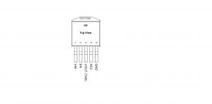
But there is one more component that regulates the voltage and that is U4. It turns 3.3 volts into 1.8 volts. In order to know how to check the voltage, you have to put a look in the data sheet. And it looks like this:

If you switch on the Wii so that the power LED turns green, you should be able to measure the input voltage of 3.3 volts at pin 1. If the controller is intact, 1.8 volts must be present on pin 3 (or on the upper contact lug). But that was exactly not the case with me. That can only mean two things:
1. The controller is defective
2. There is a short circuit
I could rule out point 2, because then the controller would get very hot. But that was not the case with me. With that the error was found. The 1.8 volts are necessary, among other things, to generate video images and also supply other circuit components on the Wii. So I tried to get a new regulator. But that's very difficult because nobody has such a spare part. I also asked the German repair shops, but apparently nobody does board-level repairs, they are probably limited to component / mainboard replacement. So a replacement has to be found …….
Considerations and Challenges
A functioning regulator could be unsoldered from an intact Wii and reinserted into the defective Wii. But that is not entirely without risk. The regulator U4 could break when unsoldering or soldering it in, and I am reluctant to break one device in order to repair another. When looking for replacement types with similar properties to the original, I also failed. There was always some show stopper. The problem here was that it is very difficult to get a regulator that has the same pinout. There are some LDOs, but they have ground and not VOUT on the housing. But you have to solder such a regulator onto the circuit board, because this also cools the component.
What exactly do you need and what is the starting point?
Input voltage = 3.3 volts
Output voltage = 1.8 volts
Output current = 2.5 Amperé max. (You don't need 2.5 A at the point in the Wii, but you should rather create the same specifications; the manufacturer will have thought of something)
Installation height = approx. 3 -4 mm (it is very tight in the Wii)
Unfortunately, I couldn't find a suitable component, so I decided to do a small hack. There are small step-down modules to buy. These can convert a higher input voltage to a lower output voltage and have no high power loss. These modules are very small and deliver a maximum of 3A. The only disadvantage is that you need a higher input voltage than 3.3 volts in order to generate a stable 1.8 volts.
That's why the 3.3 line in the Wii is out of the question and I don't know exactly whether the 5 volts in the Wii can carry that. That's why I decided to use the Wii's primary 12 volt voltage. With that I am within the specs of the converter. I bought a converter with an adjustable output voltage because it was the smallest I could find. But there are also some with a jumper / solder bridge, where you can set the desired output voltage (recommended for beginners).
That would be something here:
https://www.ebay.de/itm/232886432321
or the one I took:
https://www.ebay.de/itm/353801259294
However, it has to be set to 1.8 volts before it is built into the Wii. Otherwise the Wii will be damaged. This is a step-down converter based on an MP1495 chip. But there are also many others. You should only have an output voltage of 1.8 volts and 3A output current. It must be possible to use 12 volts as input voltage. If you use this module, we now have the effect that as soon as the Wii is connected to the power supply, it immediately generates 1.8 volts.
There are some electronic circuits that will damage if one part is live and the other is not. So there is still a trick to be used.
The converter modules have an "enable" input. If a positive voltage is applied to this, the module generates 1.8 volts. If not, it doesn't create any output. You just have to connect this "enable" input to the 3.3 volts that fed the old regulator. If you switch on the Wii, the 3.3 volts are activated. These are now coupled with the new converter and this activates the 1.8 volts. Thus, the step-down converter behaves just like the old controller. It even has the advantage that it did not generates big heat loss and is therefore much more efficient. The converter chips also have various protective functions against short circuit, heat and voltage fluctuations, so that this part has been improved, so to speak.
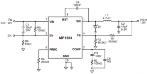
Unfortunately, the “enable” input is permanently wired on the converter modules, so that it has to be modified slightly. To do this, you have to unsolder the SMD resistor that connects the "enable" input with Vin and connect a new resistor (47 - 100 kiloohms) to the 3.3 volt line of the Wii. Here is a circuit diagram so that you can imagine it better:

Source: Datasheet MP1584 (monolithicpower.com)
Here you can see the resistor R5. This must be unsoldered. Now you only need to connect the input (here EN) to the 3.3 volts of the Wii. Vin must be connected to the Wii's 12 volt rail. Of course, the ground connection should not be missing either. Then just connect Vout to the 1.8 volt rail of the Wii and then everything is ready.
Implementation
If you have got a suitable converter and disconnected the resistor from the "enable" input as described above, you can start installing it in the Wii. The revision of the Wii board doesn't really matter because every revision has the same regulator on U4.
In order to create some space, it makes sense to remove U4, C3, R1 and R2. The two resistors and the capacitor are no longer required. I do not recommend soldering the U4 with hot air, but with a soldering iron. To do this, you can heat the pinns of the defective controller pin by pin with the soldering iron and carefully lift it off the circuit board until they no longer have any contact. Then you can heat the soldering lug at the top of U4 with a soldering iron and some flux or solder until you can lift it off.
Then remove old solder tin residues with a desoldering braid and clean the whole thing with isopropanol.
Important: Please be sure to put a plastic sheet (0.3 0.5mm) between the Wii mainboard and the converter and fix it so that there is no unwanted short circuit. It is also important that all soldered leads on the converter are not higher than the highest component on the converter module. Otherwise there is a risk of creating a short circuit with the shielding plate of the Wii.
Once you've done all of this and wired everything, the 1.8 volts should be back.
Attention: If you have bought a step-down converter that does not have a fixed voltage by jumper oder solder pad, it must first be set to 1.8 volts. Before you connect the output to the 1.8 volt supply of the Wii, you do not have to connect it and instead connect a load resistor (30 - 50 ohms, and a few watts) to the output of the converter and then use a multimeter to increase the output voltage set exactly 1.8 volts. That is required, because you must have some load on the new regulator when adjusting.
Once that's done, you can remove the resistor and connect the Wii 1.8 volt rail.
---------------------------------------------------------------------------------------------------------------------
It all sounds pretty wild, but it's relatively easy.
Maybe someone here has a Wii that lacks 1.8 volts.You can then send it to me, then I would make a YouTube video of it and then send the Wii back.


