Hi guys,
I'm new in the forum, and I'm trying to fix a damaged Nintendo switch.
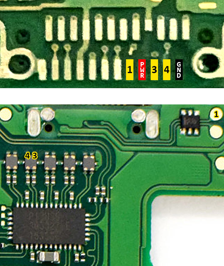
I bought the Nintendo as faulty, and it wasn't charging. If I add a charged battery, the switch works perfectly, so after testing and inspecting, I noticed that the idiot that sold it to me attempt to replace the USB-C.
Unfortunately, as you can see yourself (C), he almost destroyed the board, and one of the pad was missing (A).
Now my question is: since the damaged pad is just with one, is there any other part on the board where I could bridge that pin?
I'm tempted to scratch the covering next to the missing pad (B) and bridging it in there, but if that won't work any suggestion?
Also, do you think that the damage on (C) could cause problems?
And last but not least do someone know the specs for the resistor in green? I know it is a 0402 in size but not sure about the specs.

I'm new in the forum, and I'm trying to fix a damaged Nintendo switch.
I bought the Nintendo as faulty, and it wasn't charging. If I add a charged battery, the switch works perfectly, so after testing and inspecting, I noticed that the idiot that sold it to me attempt to replace the USB-C.
Unfortunately, as you can see yourself (C), he almost destroyed the board, and one of the pad was missing (A).
Now my question is: since the damaged pad is just with one, is there any other part on the board where I could bridge that pin?
I'm tempted to scratch the covering next to the missing pad (B) and bridging it in there, but if that won't work any suggestion?
Also, do you think that the damage on (C) could cause problems?
And last but not least do someone know the specs for the resistor in green? I know it is a 0402 in size but not sure about the specs.