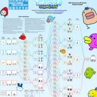
Look Ma! My Welcotchi is a part of the metaverse!
In case you weren't aware, a new Tamagotchi was released over the weekend, the Tamagotchi Uni. The main difference this time around was the inclusion of wifi. This allows for firmware updates, time-limited items, and to interact with the "tamaverse." While the tamaverse is mostly offline, you're able to interact with other tamas online (marry them off, etc.)
^ This is Rash. He will most likely die because I have a full-time job and he sleeps from 8pm to 8am.
This thread will be to document what I've found (and if anyone wants to join in, they can). The goal (at least at the moment) is to grab any firmware updates/document how the Uni talks with the servers.
What I've found out so far:
It uses TLS 1.2
Only 2.4Ghz networks supported
The first URL it checks is apiuni-tmgc.tyb.jp
The cloud server is on AWS Northeast-1 in Japan
The wireless module claims to be made by ESPRESSIF SYSTEMS (SHANGHAI) CO., LTD. so it's an ESP32 MCU
Doesn't seem to have Bluetooth
According to the manual, firmware downloads are as large as 9.5mb
https://apiuni-tmgc.tyb.jp/ jumps to any one of the following IPs (this could of course change with an update):
35.79.59.252
52.199.19.128
35.78.56.100
54.95.78.200
18.182.80.137
52.194.44.193
35.73.234.2
18.181.64.19
It tries to connect to the server 5 times before giving up
One annoyance is that if you choose "automatic" for the network settings, it's impossible to set the DNS server separately. If you choose manual though, it doesn't allow you to set DHCP for the IP. To get the network dumps so far, I've had to create my own mitm hotspot using wihotspot on Ubuntu. While I've done similar things before, for some reason the Uni gives an error when connecting. Wireshark isn't giving me a whole lot of info as to why though. The server just resets the connection, and then the Uni tries again.
Post automatically merged:
Day 2! (Yes, I know it's the same day, but I did the research for my first post yesterday)
Rash isn't dead surprisingly. However, he's seemed to have de-aged:
He's also getting into social media which I am concerned about...
Thanks to u/siabe on Reddit, I know a lot more about the hardware itself:
The Wifi Module is an ESP32-S3-WROOM-1
The SoC is an Xtensa LX7
1300mah battery
What I've learned today:
My Uni is currently on firmware 1.0.2.
The apiuni server also points to 54.250.16.101. When you connect to the apiuni server, it gives a redirect to one of the IPs.
When you connect to the apiuni server, whichever IP it sends back is locked on until either A) You disconnect, or B) a new DHCP lease is sent. So if you manually set the IP, never let it go to sleep, and never leave the range of your router, it will always connect to the exact same server.
A new DHCP lease is requested each time the Uni wakes from sleep.
When checking for updates, the Uni loves exchanging certificates. After every three or four transmissions of application data, it verifies the server certificate. It makes me wonder if there's no checks done by the Uni itself on whether a firmware image is valid.
The server certs are generated by AWS, not Bandai specific. However, The ESP32 module declares itself as belonging to Bandai when it first connects.
When you download items, all it's doing is downloading from an AWS S3 bucket (after exchanging a server cert twice). Presumably it is hashing the item code you've given it and identifying that hash with a specific s3 bucket.
I downloaded the "hip-hop cap" and it looks like it's 2kb in size. No idea yet if every item is exactly 2kb or not
I explored the "tamaverse" a bit, and most things are closed at the moment. Potentially these open in a software update down the line?
If it was possible to install a new CA on the Uni, I could get a lot more info out of it.
When you download the "news," it looks like it downloads 40KB of data every time, and the promotional items/gifts are embedded in that.
Beyond that, I'm kind of at a standstill until we can get an mitm CA installed on the Uni. Nearly everything that the Uni does is communicated via TLS, and we need to be able to to decrypt that to get more info on its workings.
As far as I can tell nobody's actually identified the Uni's main display/logic chip yet, only the ESP32-S3 wifi module is confirmed. I was assuming it'd be the same chip family as the Pix (which has accessible SPI flash via debug pads), but that's a guess, not a fact, and I don't want to send anyone shopping for tools based on it.
Marcelmono's power-off mod research already found test points on the board for the power regulator chip. Does anyone know if their writeup/photos show the main SoC's part number? That'd be the free way to confirm what we're actually dealing with before anyone opens anything up.
Separately, I want to help on the non-destructive side for now (I'm not willing to crack open my daily Uni for this). Maybe we run our own MITM capture and see what happens when it gets a cert it shouldn't trust, just to test whether validation is actually solid or there's a soft spot. If it turns out we do need board-level access down the line, maybe we can look for a dead/broken used unit to sacrifice rather than risk a working one.
Edit:
Found something that answers the "what's the main chip" question, from a couple Japanese sources that don't seem to have made it into English-language Tamagotchi circles yet:
1) A Japanese semiconductor analysis firm (Tecanarie/テカナリエ) did a die-level teardown for EE Times Japan, comparing it to Apple's M2 Ultra as a bit.
2) A much more detailed hobbyist teardown by tomorrow56 (ThousanDIY), originally published in the Japanese electronics magazine I/O, goes board-level.
Key findings from those:
- There's no separate "game logic" chip like the Pix has. The ESP32-S3-WROOM-1 module IS the main processor — it does wifi, display, and game logic, all on one chip. tomorrow56's writeup labels it directly as 「ボトラタ:無線モジュール(メインプロセッサ)」 ("the wireless module is the main processor").
- That module's specs: dual-core Xtensa LX7, 512KB SRAM, and 16MB of SPI flash built in. Not mask ROM — regular flash, same as any ESP32 dev board.
- Most importantly: tomorrow56 found and photographed test pads on the back of the board, explicitly identified as exposing UART plus the signal for triggering the chip's Download Boot mode. That's just the standard Espressif bootloader entry point — the same one esptool.py talks to on every ESP32 project. No glitching or decapping needed to get flash access, just normal ESP32 dev workflow.
Given that, the procedure to actually dump the flash should be:
1. Open the case and locate those test pads (cross-reference tomorrow56's photos for exact placement — I haven't pinned down which pad is which signal yet).
2. Identify GND, TX, RX, and the boot-mode pin (typically GPIO0 on ESP32-series chips — needs to be pulled low during reset to enter download mode).
3. Touch test probes (pogo pins or fine clips, no soldering needed) from a cheap USB-serial adapter to those pads.
4. Hold the boot pin low while power-cycling/resetting so it boots into Download mode instead of running the app.
5. pip install esptool, then read out the full 16MB: esptool.py --port [your port] --baud 115200 read_flash 0 0x1000000 uni_dump.bin
6. From there we've got the actual firmware to dig through — partition table, trust store/certs (answers the CA question from earlier), and hopefully the asset/character data format.
Haven't tried this myself yet on a real unit, posting the plan before touching anything in case someone's already further along or sees a problem with it. Anyone want to confirm pad locations against their own board before I commit to probing mine?
Good morning everyone, to clarify first here, I'M NOT AN EXPERT, NOR RESPONSABLE IF I DAMAGE ANYONE'S TAMAGOCHI UNI OR DEVICES.
With that clear, i have reciently gotten invested with the Tamagochi Uni hardware (As im a hardware nerd per-se, but whatever) and i have made some ideas of how to do it.
As we know:
Uni Hardware is:
The Wifi Module is an ESP32-S3-WROOM-1
The SoC is an Xtensa LX7
370mah battery (Actually that value according to a FCC aplication (ID is PQ3SWALLOWUNI or PQ3 SWALLOWUNI)
The SOC has an external SPI Flash (not a shocker i know) and guessing being BANDAI, they would have forgotten to disable both UART and SPI Read permissions (since well, it kinda needs it)
AND, THE DIAGRAM OF HOW THE ESP32 IS CONNCECTED IS KINDA EASY TO SEE DUE TO the internal photos document. FCC Internal Photos for SWALLOWUNI
Besides the ESP32-S3-WROOM-1being the only interesting thing (and the one that handles everything), the thing also has an accelerometer.
Anything else is just basic or regular components (Power Block and DAC/Audio Circuit).
And that the ESP32-S3-WROOM-1 Is kinda a normal unit with only BANDAI/ Tamagochi Software.
I know that this information will probably be useless, but i wanted to make a post anyway... And if it serves useful on the future, i guess its neat i did something.
EDIT: Found that BANDAI Technically has the pins for TX and RX enabled
As far as I can tell nobody's actually identified the Uni's main display/logic chip yet, only the ESP32-S3 wifi module is confirmed. I was assuming it'd be the same chip family as the Pix (which has accessible SPI flash via debug pads), but that's a guess, not a fact, and I don't want to send anyone shopping for tools based on it.
EDIT 2: It seems that the only logic thing is the ESP32. No other chips or companents, besides PWM and Accelerometer.
EDIT 3: Fixed a link.
Post automatically merged:
DISCLAMER: I DONT OWN THE DEVICE (AT THE TIME OF WRITING) SO I CANT TEST THESE, THESE ARE JUST IDEAS AND ESPECULATION. IF IM WRONG, I WILL TAKE THE FACT, NOT THE BLAME. TEST UNDER YOUR RISK.
I have an idea. Since we know what the pinout of the ESP32 is and looking at the PCB, It seems that oddly enought Bandai left 4 pins of the back of the device that are:
Close to the ESP32 Module (I'll refer to it as ESP32 as its easier to name it.)
Seem that could be for UART (4 Pins: GND, PWR/3.3 V (Since well, the patchi OFF uses a exposed 3.3 V Line that could be wired)
Since i guess, we could probe these with a multimeter, we could figure out where the power rails for that are.
BUT, YOU MAY ASK OR SAY: "Cool N4A, BUT WHERE DO WE GET TX AND RX?!"
Worry not, i have another Idea. Since as GlossPixie said:
Given that, the procedure to actually dump the flash should be:
1. Open the case and locate those test pads (cross-reference tomorrow56's photos for exact placement — I haven't pinned down which pad is which signal yet).
2. Identify GND, TX, RX, and the boot-mode pin (typically GPIO0 on ESP32-series chips — needs to be pulled low during reset to enter download mode).
3. Touch test probes (pogo pins or fine clips, no soldering needed) from a cheap USB-serial adapter to those pads.
4. Hold the boot pin low while power-cycling/resetting so it boots into Download mode instead of running the app.
5. pip install esptool, then read out the full 16MB: esptool.py --port [your port] --baud 115200 read_flash 0 0x1000000 uni_dump.bin
6. From there we've got the actual firmware to dig through — partition table, trust store/certs (answers the CA question from earlier), and hopefully the asset/character data format.
Haven't tried this myself yet on a real unit, posting the plan before touching anything in case someone's already further along or sees a problem with it. Anyone want to confirm pad locations against their own board before I commit to probing mine?
But inestead of probing like crazy/ risk damage to a Poor Uni unit (as it's suffering wasn't enough) To figure out the pins, i have made a little diagram/idk what that (Maybe poorly) figures out how the ESP32 is wired on the PCB.
My idea is as follows. (SINCE I DONT OWN THE DEVICE AT THIS POINT)
Use the diagram to find UART Pins, and my best bet is the 4 Close pins under the board. since i guess a JIG or a tool that poked those was used.
After finding the pins, try and talk to the ESP32.
Read eFuses flags (If any)
And then dump the SPI flash.
Here's the SPI Flash. I cant really touch it, becouse I DONT OWN IT :c (i wish i would btw)
After googling the SPI... Or should i say... NOR!..
Well, back on point i can say this (Which we kinda knew)
Its 16 MB (128 Mbit)
Its NOR.
In this case its made by GigaDevice (GD25Q128ESIG). FOR THIS CHIP ONLY IT SUPPORTS OR HAS:
Uniform Block sectors of either 4/32/64 K-Byte.
128-bit Unique ID for each device.
Serial Flash Discoverable parameters (SFDP) register
It also has "Software/Hardware Write Protection"
"Write protect all/portion of memory via software"
"Enable/Disable protection with WP# Pin"
"Top/Bottom Block protection"
And sadly, OTP Protection. "3x1024-Byte Security Registers With OTP Locks"
But on the other hand:
"The GD25Q128E (128M-bit) Serial flash supports the standard Serial Peripheral Interface (SPI), and the Dual/Quad SPI: Serial Clock, Chip Select, Serial Data I/O0 (SI), I/O1 (SO), I/O2 (WP#), I/O3 (HOLD#/RESET#). The Dual I/O data is transferred with speed of 266Mbit/s, and the Quad I/O data is transferred with speed of 532Mbit/s."
And the Pinout is on the datasheet. (OFC!)
We also have a block Diagram.
And how it stores data.
I'll read the documentation of the chip to see what's actually all about.
Post automatically merged:
Also, if you wanna contribute, You can Join: Discord Server.
Post automatically merged:
Once again, N4A here and as i said before: DISCLAMER: I DONT OWN THE DEVICE (AT THE TIME OF WRITING) SO I CANT TEST THESE, THESE ARE JUST IDEAS AND ESPECULATION. IF IM WRONG, I WILL TAKE THE FACT, NOT THE BLAME. TEST UNDER YOUR RISK.
So i have been reading about the especific ESP32 Used on the Tamagotchi Uni (ESP32-S3-WROOM-1)
And i have concluded the following:
Besides Wi-Fi, the chipset supports and has bluetooth (Bluetooth LE: Bluetooth 5, Bluetooth mesh), but is "never used" (Unless the phone Wifi pairing uses it, i cant test this as of the time of writing i dont own a device.) (Tamagotchi Uni Manual (ENG)
Internal co-existence mechanism between Wi-Fi
and Bluetooth to share the same antenna
36 GPIOs ( Let's say 3 are used by the buttons, 4 by the screen (i can count 6 pins on the connector and i guess GND and 3v3/3.3V are shared from somewhere else), The accelerometer (lets say 4-6), so that leaves us with 24-22 GPIO Ports free, which can be traced by looking at the ESP32's underside, but no worry, no need to desolder yours since theres a diagram on the reverse side where you can look at the pins, and for what i guess is our uses there's no need to use them.)
384 KB ROM
512 KB SRAM
16 KB SRAM in RTC
16 MB NOR/SPI Flash (So that makes this one a ESP32-S3-WROOM-1-N16R8 or ESP32-S3-WROOM-1-N16R16VA. Although if bandai customized it "For customization of ESP32-S3-WROOM-1-H4, ESP32-S3-WROOM-1U-H4, and ESP32-S3-WROOM-1U-N16R16VA, please contact us" - Extracted from the Datasheet (Page 4))
The PSRAM is embedded ("The modules use PSRAM integrated in the chip’s package." - Datasheet (Page 5))
VDD for the NOR/SPI is 1.8v ("Please note that the VDD_SPI voltage is 1.8 V for ESP32-S3-WROOM-1-N16R16VA and ESP32-S3-WROOM-1U-N16R16VA only." - Datasheet (Page 5))
And that this thing does have 8 MB or 2 MB OF RAM! Not 16... Why Bandai... When the peak was coming up...
Also something important to note is that according to the block diagram Bandai used a S3,S3R2 or S3R8. So that means... That maybe what i said above could be wrong. (Im refering to the board used, not the CPU/SoC used)
CPU, RAM, ETC (Which were figured out by other people, but data is data i guess...)
Security (AES,RSA, Secure Boot, eFuses, etc)
AND MOST KEY....
The beatiful weird, cute, odd block diagram. Which i must admit is quite unique.
And we also get some of the cool I/O (Over digital I/O or GPIO):
3x UART Ports! (Factory flashing could have used one... and i have wired it out...)
2x I2C (Screen Interface and accelerometer maybe?)
1x USB Serial / JTAG Controller
1 x SDIO Host Controller with 2 slots.
A General DMA Controller (GDNA) with 5 transmit channels and 5 receive channels.
Has two Low Power CPUs:
ULP-RISC-V coprocessor.
ULP-FSM coprocessor.
And for security you may ask? Well, i can say for sure that it's packed:
Secure Boot
Flash Encryption
4-Kbit OTP (Up to 1792 bits for users, which means 2,304 bits are strictly reserved, and the leftovers could have been used by Bandai for locking UART or high-security control switches, cryptographic keys, and device identity flags that dictate how the bootloader and system recovery operate.... But i guess Bandai wouldn't go so far, and once again i remind you this is pure especulation, so maybe they did or maybe they didnt. Better safe than sorry.)
A Hardware accelerated cryptographic engine for:
AES-128 and 256 (FIPS PUB 197)
Hashing (FIPS PUB 180-4)
RSA
RNG (Random Number Generator)
HMAC
Or Digital Signing.
Ignoring that and looking at the nomenclatures:
I can conlude that Bandai used:
A model that was either customized by espessif (Not likely since Bandai uses lots of off the shelf parts since forever. like the Sonix SNC73410 MCU found on the Paradise)
Or any of the S3 models (S3,S3R2 (2MB RAM), S3R8 (8 MB OF RAM))
This is all i can conclude unless i get a picture of the Chip used, since the filings dont have a very high quality pic.
But what i can add is that my theory of the pins being conncected to a test point on the mobo is correct since if i look at the block diagram (UNI Block Squematics):
Yes. The TP3 is RX and TP4 is TX. So that also means that my theory of the JIG being real is possible.
I have news to share, It seems that on some areas (Discord Servers and such) some people have discovered that:
UART IS possible, but leads to a console.
The ESP-32 has secure boot enabled and its SPI/NOR IS encrypted.
That Bandai at much js contacted a design company to make the Device.
And for the moment the ESP-32 Device family that the Uni uses has been undefeated.
This doesnt mean ofc that im giving Up... If anything im going to try and get more help, research, data and people to help me. But if the info above resulta useful (but maybe for the people that i have talked to see It more as a recap/basics of what they know of the Uni.)
In resume, we need more people and help. So if anyone has any ideas or anything that could help us (Knowladge, Devices, anything) is welcome. I know this is a far cry into the void, but if you the render have something that can help this, please share It...
It’s about that time of year again where I check in with the community to see if we can get the front page aligned with what people are interested in knowing and what...
WiiCompiled is a new project that lets PC gamers play Mario Kart Wii natively on PC without emulation. Using static recompliation to convert the code into native PC...
Images for the rumoured Zelda-themed limited edition Switch 2 for The Legend of Zelda's 40th Anniversary have started to leak online.
The leak shows only the...
After being announced last year, the fan-made remake Gamma Emerald has finally gotten its first early access release. A complete rebuild of fan-favourite Pokemon...
The long awaited Grand Theft Auto VI Extended Look gameplay trailer has finally dropped on YouTube. As you all know, it had dropped 6 hours earlier on Netflix, and...
Though we knew all the way back in May that this was coming, the exact numbers remained a mystery for prospective Nintendo gamers in the UK. If you happen to have...
Thanks to the recent decomplication efforts; The Minish Cap 3DS brings the Game Boy Advance classic Zelda title to your 3DS.
The port takes full advantage of the 3DS...
In the wake of Sony's shift to a digital-only ecosystem within the next year, Xbox have today announced a surprising scheme. Aiming to offer physical buyers the same...
GBAtemp is and always has been an independent community. Since 2002 our staff have voluntarily kept the site running, added new forums, features, provided constant...
To celebrate its 25th anniversary, XBOX has launched pre-orders for the XBOX 25th Anniversary Collection. For the occasion, the trailer below was aired.
This...
It’s about that time of year again where I check in with the community to see if we can get the front page aligned with what people are interested in knowing and what...
After being announced last week, the first of two broadcasts is set to go live later today with a stark focus on The Legend of Zelda and its 40th anniversary...
In the wake of Sony's shift to a digital-only ecosystem within the next year, Xbox have today announced a surprising scheme. Aiming to offer physical buyers the same...
Though we knew all the way back in May that this was coming, the exact numbers remained a mystery for prospective Nintendo gamers in the UK. If you happen to have...
Images for the rumoured Zelda-themed limited edition Switch 2 for The Legend of Zelda's 40th Anniversary have started to leak online.
The leak shows only the...
The long awaited Grand Theft Auto VI Extended Look gameplay trailer has finally dropped on YouTube. As you all know, it had dropped 6 hours earlier on Netflix, and...
It is with a heavy heart that I announce the departure of our beloved Chary from the position of Chief Editor. Chary took over early 2021 and has done a wonderful job...
After being announced last year, the fan-made remake Gamma Emerald has finally gotten its first early access release. A complete rebuild of fan-favourite Pokemon...
Thanks to the recent decomplication efforts; The Minish Cap 3DS brings the Game Boy Advance classic Zelda title to your 3DS.
The port takes full advantage of the 3DS...
GBAtemp is and always has been an independent community. Since 2002 our staff have voluntarily kept the site running, added new forums, features, provided constant...