Wii U Stuck on Logo

ChefVortivask

Well-Known Member
OP
Member
Joined
Apr 3, 2023
Messages
340
Trophies
0
Age
26
XP
598
Country
United States
Hello everyone,

First time poster here. I decided to make this post since I am having issues with my Wii U. Currently, my Wii U will not boot up to the main menu. It stays stuck on the Wii U logo indefinitely.

There are a few things to note about my console. The console is the black 32 gb model. I believe it was bought during the 2012 holiday season (release) as we were expecting to play Pikmin 3 before it got delayed. The system has never been modded in any fashion. It was not the most heavily played console, and I can't even give a good estimate of when it was last used (at least more than 3 years).

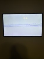
I have already tried doing the UDPIH, however it does not seem to be working. When using the second recovery menu, I get a white screen with some blue lines (see attached image). I believe this is similar to what @fadafwet described in his post. I was able to get the logs from the system, which I have attached to this post. Any idea what the issue may be and how to fix it? Any help would be much appreciated.
 

Attachments

  • Garbled Screen.jpg
    Garbled Screen.jpg
    1.5 MB · Views: 103
  • logs.zip
    63.9 KB · Views: 90

ChefVortivask

Well-Known Member
OP
Member
Joined
Apr 3, 2023
Messages
340
Trophies
0
Age
26
XP
598
Country
United States
Would isfshax be something I could try, at least as a means to check if the Wii U itself is fine, or can I not do that since the eMMC has been disabled?
 

ChefVortivask

Well-Known Member
OP
Member
Joined
Apr 3, 2023
Messages
340
Trophies
0
Age
26
XP
598
Country
United States
I’m going to double check all the wiring for the pico to make sure nothing has come loose. I’ve always handled it carefully and never did notice a wire come loose (except for one time, but I just resoldered them to the pico). Is it possible that a loose wire could be responsible? I’ve been under the assumption that if there was a loose wire, de_Fuse simply wouldn’t work.
 

ChefVortivask

Well-Known Member
OP
Member
Joined
Apr 3, 2023
Messages
340
Trophies
0
Age
26
XP
598
Country
United States
I noticed in that last log that it doesn’t even look like the card showed up at all. Before at the very least we could see the card show up and see the size, but unless I overlooked it, I’m not seeing that. Because of that, I think it might be worth double checking the supply voltage. Maybe somehow the connection isn’t the best, or perhaps it’s not quite right since I soldered the wire for the SD card adapter?

Edit: I actually noticed that it hasn't shown the card size since I've been using the version of minute that keeps the bus width to 1, so maybe that's just something inherent to this version of minute? I'll try the last version of minute I used since I know that the card size did show up in that.
Post automatically merged:

That is not a problem with the pico. it's something between the the SoC and and the card
Has something like this been reported before on this site or elsewhere (at least from what you’ve seen)?
 
Last edited by ChefVortivask,

ChefVortivask

Well-Known Member
OP
Member
Joined
Apr 3, 2023
Messages
340
Trophies
0
Age
26
XP
598
Country
United States
Just brainstorming here, but we did notice a slight improvement when using the SD card adapter. It still didn’t work, but it was better than when I used the slot, so maybe there is an issue with the slot that’s causing it to fail? I’m not sure if that makes sense though since I didn’t detect a short between any two lines.
 

SDIO

Well-Known Member
Member
Joined
Feb 13, 2023
Messages
2,417
Trophies
0
Age
28
XP
1,683
Country
Germany
If the slot doesn't cause a short, then it shouldn't interfere. Also I don't think the adapter makes anything really better, it just seems that one of the signals is so bad and just on the edge of working and not working
 

ChefVortivask

Well-Known Member
OP
Member
Joined
Apr 3, 2023
Messages
340
Trophies
0
Age
26
XP
598
Country
United States
it just seems that one of the signals is so bad and just on the edge of working and not working
Thats...interesting. Is there something that can cause a bad signal other than a poor solder joint? I don't think we have enough information to say which signal(s) it is.
 

ChefVortivask

Well-Known Member
OP
Member
Joined
Apr 3, 2023
Messages
340
Trophies
0
Age
26
XP
598
Country
United States
I had an idea that I'm not sure would work, but would it be possible or even worth trying if I were to take some of the tin magnet wire I have and solder it from the vias for CLK and CMD to the appropriate spots on the NAND-AID? Even though my measurements with the multimeter indicate that the connection is good, maybe something is happening that is resulting in the connection looking good when it isn't? Doesn't seem to make much sense when worded like that, but could something be giving me a false positive? This sort of reminders me of a situation I had about 4 months back with an amp I installed in a GBA. There was a joint that no matter how much I tried soldering it, I just couldn't get a good connection, as indicated by my multimeter. I had to solder a jumper wire from another point on the board to the contact on the amp for it to finally work. Maybe something similar would work here? There's definitely more than a few holes on the board I could snake the wire through to keep them short, but then the question is how short do they need to be for the signal to stay intact.
 

SDIO

Well-Known Member
Member
Joined
Feb 13, 2023
Messages
2,417
Trophies
0
Age
28
XP
1,683
Country
Germany
maybe when you press with the probe you press a broken joint together or something like that
Post automatically merged:

Try measuring from the SD adapter to the other side of the via, so you are not pressing against the nand aid
 
Last edited by SDIO,

ChefVortivask

Well-Known Member
OP
Member
Joined
Apr 3, 2023
Messages
340
Trophies
0
Age
26
XP
598
Country
United States
Good idea. I'll also send a picture of my adapter just in case I flipped a wire or something. I was careful to make sure I didn't, but a second set of eyes wouldn't hurt.

As for testing the connections, is there another place besides the leg of that one component (not sure what it is) that I can test for continuity with 3V3? Obviously a test of voltage will tell me all I need to know, but before I do that, I think it would be a good idea to test continuity.
 

ChefVortivask

Well-Known Member
OP
Member
Joined
Apr 3, 2023
Messages
340
Trophies
0
Age
26
XP
598
Country
United States
I checked the resistance for every connection using the vias and the pins of the SD card adapter, and everything looked fine. Resistance values were very close to 0 (around 0.3 ohms).
 

ChefVortivask

Well-Known Member
OP
Member
Joined
Apr 3, 2023
Messages
340
Trophies
0
Age
26
XP
598
Country
United States
Although I don’t think it’s likely, is it possible that since the pads for CLK and CMD were ripped off that the connection to the main chip (SoC I believe, sorry if I’m wrong) was damaged? We know that all the connections from the castellated vias seem to be good, but for whatever reason, something seems to be wrong with the CLK and/or CMD line. This is assuming that nothing somehow got fried on the board.
 

Ysecond

Well-Known Member
Member
Joined
Apr 27, 2023
Messages
187
Trophies
0
Age
26
XP
487
Country
China
If there's no clue,would you try removing the nand-aid and measuring the resistance?measure the resistance between each line and GND. Of course, this is my choice, removing NAND-AID is very difficult.
I just feel that when there are no clues, maybe we should start from the beginning again.
Can you also provide some HD pictures?
 

ChefVortivask

Well-Known Member
OP
Member
Joined
Apr 3, 2023
Messages
340
Trophies
0
Age
26
XP
598
Country
United States
Alright so I have some good news (at least I think so). When I was testing resistance and continuity using those vias under the SoC, I discovered that there was a short between CLK and CMD. After an inspection, I noticed a very tiny bridge of solder between the CLK and CMD castellated vias on the NAND-AID. I think I forgot to test for shorts after I soldered the SD card adapter to the NAND-AID, so apologies for my stupid oversight. I fixed the short and then retested resistance and continuity. Nothing appears to be shorted to anything and resistance measurements all look good. All four data lines as well as CLK and CMD measure around 1 ohm when measuring either via to via or via (under SoC) to NAND-AID, so that means those traces seem to be fine. I decided to go ahead and try minute again since the last time I did it, CLK and CMD were shorted. The results look far better than the last time I did it. The card is actually detected and the correct size shows up. Patch & boot still resulted in an iosPanic, but since the results seem so much better with the card adapter, I'm leaning towards the problem being something with the card slot.

Also, I don't believe CLK and CMD were shorted before I soldered on the SD card adapter. I had tested for shorts several times and I believe the short was introduced when I soldered on the wire for the CLK connection.
 

Attachments

  • 122923_Before menu_short fixed.txt
    3.9 KB · Views: 11
  • 122923_Patch & boot.txt
    29.4 KB · Views: 12

Site & Scene News

Popular threads in this forum

General chit-chat
Help Users
  • No one is chatting at the moment.
    SylverReZ @ SylverReZ: @K3Nv2, Honestly a great Eminem song.