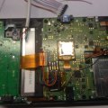
Hardware N3DS NAND backup possible, I hope.

mvmiranda

Well-Known Member
Member
Joined
Oct 29, 2013
Messages
1,457
Trophies
1
Location
Brazil, Sao Paulo
Website
www.gamemod.com.br
XP
1,673
Country
Brazil
oh yeah, replacing the card slot etc will be much easier....guess they had too many card slot repairs to do so designed them to be easier to repair......tbh there is a trick not to have to disassemble the original 3ds completely, by just popping the bottom LCD out, then you can access CLK without taking the board out ....so no fiddling with the top LCD ribbon cables....that trick saves a bunch of time doing the original 3DS's

Hmm! Now THAT is a handy tip I liked! :)
Thx!

BTW, I've found this Transcend card reader. It's slightly different that the one Avalynn used. He used a TS-RDP5K and this one is, according to the seller, TS-RDP5.
http://produto.mercadolivre.com.br/...-usb-transcend-p5-sdhc-sdxc-microsdhc-mmc-_JM
Will it work?
 

gamesquest1

Nabnut
Former Staff
Joined
Sep 23, 2013
Messages
15,153
Trophies
2
XP
12,247

hundshamer

Well-Known Member
Member
Joined
May 22, 2009
Messages
1,810
Trophies
0
XP
924
Country
United States
yeah, just for the standard.normal sized n3ds, the XL pinout is definitely correct, tbh the n3ds xl is somewhere between the og 3ds, and the 3ds XL in terms of trickyness, solder points are easy enough, but needing to remove the motherboard makes it a slightly longer job than doing a original XL

Don't forget the wrist strap on the original XL made for a perfect hole for the mod, whereas the N3DS XL is like the original 3DS as you have to create a hole for the port. Also I used the Transcend Avalynn linked to.
 
  • Like
Reactions: gamesquest1

Avalynn

I'm here to learn and help.
OP
Member
Joined
Feb 23, 2014
Messages
407
Trophies
0
Age
35
Location
CA
XP
297
Country
United States
Sooo it's taken me a little bit of time to get this to work, but I've gotten my microSD car reader and micro USB port placed into my N3DS XL, not very prettily, but it reads and charges. Took me a bit to find a working microSD card reader as most of the ones I had wouldn't the eMMC. I'll post pictures and information hopefully today.
 

kelroy

Well-Known Member
Newcomer
Joined
Jan 10, 2015
Messages
61
Trophies
0
Age
32
XP
80
Country
Avalynn if you want i can help you looking for a chipset driver that can read an standar mmc, and integrate this in a pcb. With that we probably can just get out the usb for read on the computer.

I got so much experience doing that things, on my last project i desing my own 3ds printer pcb board.

So if you want, we can try that.

PD: For make the pcb i use the Kicad.
 

Avalynn

I'm here to learn and help.
OP
Member
Joined
Feb 23, 2014
Messages
407
Trophies
0
Age
35
Location
CA
XP
297
Country
United States
Avalynn if you want i can help you looking for a chipset driver that can read an standar mmc, and integrate this in a pcb. With that we probably can just get out the usb for read on the computer.

I got so much experience doing that things, on my last project i desing my own 3ds printer pcb board.

So if you want, we can try that.

PD: For make the pcb i use the Kicad.
I use Eagle Cad for all the PCBs I make myself, I've played with KiCAD as well :lol: , I've designed a couple board myself for various projects. I should get my boards sent out but usually they are one off so I just make them here in my tiny lab :ha:. I'm not sure on the controller used yet, I'm just playing around with different microSD card readers I have laying around. I use a simple adapter board from microSD to a 2.54mm header and connect that up to the N3DS so see what works and what doesn't without having to gut each one.
 

kelroy

Well-Known Member
Newcomer
Joined
Jan 10, 2015
Messages
61
Trophies
0
Age
32
XP
80
Country
Hahaha, you are like me. I got a mini lab too, just for get funny on my free time. Maybe if we open the sc-card reader that works we can find an mmc controller that works properlly. But normally they erase the chip numeration by laser.

I gonna work with this too Avalynn, and start to make a mini design with a generic mmc controller.

Here we got a nice pdf of texas instrument about how the controller works with :

http://www.ti.com/lit/ug/sprufo6a/sprufo6a.pdf
 

Avalynn

I'm here to learn and help.
OP
Member
Joined
Feb 23, 2014
Messages
407
Trophies
0
Age
35
Location
CA
XP
297
Country
United States
Hahaha, you are like me. I got a mini lab too, just for get funny on my free time. Maybe if we open the sc-card reader that works we can find an mmc controller that works properlly. But normally they erase the chip numeration by laser.

I gonna work with this too Avalynn, and start to make a mini design with a generic mmc controller.
So I popped one open that works, and it uses a GL827 by GENESYS LOGIC, though this one uses the LQFP - 100, if I could sources the other one that wouldn't be bad, but not sure on the cost of the chips. This is from a $4 microSD reader with board, chip, external components, and a crystal oscillator.

I am not going to post the specific card reader until the other batch comes in because there are different models of this and I am hoping they both use the same controller. So it might not be terrible to just buy these and gut them at this price lol.
 

kelroy

Well-Known Member
Newcomer
Joined
Jan 10, 2015
Messages
61
Trophies
0
Age
32
XP
80
Country
If it is small enought, ofc its better to use it hahaha. I gonna still looking, just for fun.

The TS-RDP5K its too big, right?.

A micro sd-reader will work too if we mod the pcb, right Avalynn. As i read the proccedure its the same. They should be able to read any mmc.

Will wait for your updates Avalynn.
 

mvmiranda

Well-Known Member
Member
Joined
Oct 29, 2013
Messages
1,457
Trophies
1
Location
Brazil, Sao Paulo
Website
www.gamemod.com.br
XP
1,673
Country
Brazil
Ok, a little update:
I've trimmed the wires and they are about 4cm long, except the GND which is 9cm long.
I've soldered a micro USB to the wires and I'm using the same SD cable I use for my old 3DS XL, pictures bellow:

PS: I've insulated the microSD metal parts before fitting it in that spot, so it's not shorting or anything.
30a42va.jpg
15qu2pl.jpg
24loi2a.jpg
The SD cable is this one here and it has ~17cm from tip to tip.
58j5x.jpg
The console still blue screens but nothing happens when I plug it to the computer.

I'll buy a Transcend reader tomorrow and test it. They are expensive as hell around here :/

Thx.
 

Avalynn

I'm here to learn and help.
OP
Member
Joined
Feb 23, 2014
Messages
407
Trophies
0
Age
35
Location
CA
XP
297
Country
United States
Ok, a little update
I've trimmed the wires and they are about 4cm long, except the GND which is 9cm long.
I've soldered a micro USB to the wires and I'm using the same SD cable I use for my old 3DS XL, pictures bellow:

PS: I've insulated the microSD metal parts before fitting it in that spot, so it's not shorting or anything.

The console still blue screens but nothing happens when I plug it to the computer

I'll buy a Transcend reader tomorrow and test it. They are expensive as hell around here :/

Thx.
Looking nice, I am sorry they are expensive :sad: I just use what I have around me lol. There are specific chipsets/controllers that seems to work I will post what I have that works.
 
  • Like
Reactions: mvmiranda

Xue

Member
Newcomer
Joined
Jan 2, 2014
Messages
15
Trophies
0
XP
107
Country
Antarctica
There's no solderless way to do this, is there? I'm guessing Nintendo has a contraption to connect to these spots, but that's too out of reach for us common folk?

I'm looking to do the hard mod to my n3DS XL, but I'm pretty hesitant. I'm not very experienced at soldering and these points are really small. I don't know anyone I could otherwise send it to, not to mention I have no money. Thankfully that alternative CLK was posted, so that ups my chances a bit. I've already taken the n3DS apart and took off the motherboard piece with the NAND. It's a THGBMBG4. I did break one of those side hook/latches for the small ribbons in the process; hopefully that won't be a problem later. Bought some fluxless solder and some 28 awg wire. I know Avalynn's been recommending 30 awg, but 28 worked out for a better price.

Could anyone give me advice on doing this well? Maybe even letting me know of someone who could do it for cheap or free?

I figure I'm going to need to do this myself though. I do have a dead motherboard that I can practice on, although I won't know at what point I'll be able to say "I'm ready."

If you don't mind, I have a few questions:
i) Can connectors from a broken computer PSU be used? The only electronic parts store in my area didn't have any of the right connectors. They did have USB connectors.
ii) People are using MicroSD adapters in the thread. Are those the only option? I've got a useless 32MB SD card here - can I gut it for this? Or because of the built in memory, will it not have pins that will be useful for connecting to?
iii) So to be sure: it's the spots soldered to wires about 4 or less inches long, which are then soldered to a female connector. Then separately, a male connector soldered to wires (limit of length?) that go into the SD case and get soldered to the pins in the SD according to the diagram Avalynn posted a few pages back. And for a 4-pin/wire connection, the spots are CMD, CLK, GND and DAT0. The only other option is all 7 spots, but that's just more risky soldering. Did I get all of that right?
iv) I just came up with an idea a while ago while thinking of custom amiibos, but unsure if it'll work. Can each spot to be soldered be surrounded by tape or modeling clay/putty/sticky tack to isolate it and prevent spots or anything else from touching? Only during the soldering and removed after.
v) Do the spots need to be scratched or "revealed?" A few posts mentioned exposing them or something similar, so I was unsure if the yellow/gold was some kind of seal to prevent a connection and needs to be taken off. Or can the spots be soldered to as is?
vi) Once soldering was finished, and a dump attempted, how could I know the NAND was successfully being backed up? A consistent size of 1.84 GB (1,979,711,488 bytes) for my THGBMBG4 NAND/eMMC? And at that point, test writing back the image to the system?

I guess that's all I can think of now. Better, before "a few questions" becomes "an essay of questions."

Thanks for any help and thanks Avalynn and the others for figuring this out.
 

Avalynn

I'm here to learn and help.
OP
Member
Joined
Feb 23, 2014
Messages
407
Trophies
0
Age
35
Location
CA
XP
297
Country
United States
There's no solderless way to do this, is there? I'm guessing Nintendo has a contraption to connect to these spots, but that's too out of reach for us common folk?
If you don't mind, I have a few questions:

I guess that's all I can think of now. Better, before "a few questions" becomes "an essay of questions."

Thanks for any help and thanks Avalynn and the others for figuring this out.

If you were in the US I'd love to help you out!

Alright so let's go!


i) Can connectors from a broken computer PSU be used? The only electronic parts store in my area didn't have any of the right connectors. They did have USB connectors.
Yes anything that can join copper to copper to form a connection can be used. You can use connectors from other things but make sure you have the matching male and female and plan where you are going to put what. Ensure enough room is there to be able to close the system back up and not add any unnecessary pressure to the motherboard or the bottom LCD screen

ii) People are using MicroSD adapters in the thread. Are those the only option? I've got a useless 32MB SD card here - can I gut it for this? Or because of the built in memory, will it not have pins that will be useful for connecting to?

No it's not the only options there are lots of options, but it stands to reason that it is the easiest at times. You can gut and old SD card but you have to make sure to disconnect the controller from the board, which in retrospect may be more hassle then it's worth.

iii) So to be sure: it's the spots soldered to wires about 4 or less inches long, which are then soldered to a female connector. Then separately, a male connector soldered to wires (limit of length?) that go into the SD case and get soldered to the pins in the SD according to the diagram Avalynn posted a few pages back. And for a 4-pin/wire connection, the spots are CMD, CLK, GND and DAT0. The only other option is all 7 spots, but that's just more risky soldering. Did I get all of that right?

Yes, the wire length limit is because you are reading high speed signals and the less resistance and less possible noise induction on the lines, the better. Yes there is only 1x mode or 4x mode as per the eMMC specifications datasheet, so either 1 DAT line or all 4.

iv) I just came up with an idea a while ago while thinking of custom amiibos, but unsure if it'll work. Can each spot to be soldered be surrounded by tape or modeling clay/putty/sticky tack to isolate it and prevent spots or anything else from touching? Only during the soldering and removed after.
The entire system needs to be disconnected and removed from the housing to work on the opposite side. You could solder each part and cover that with kapton tape or the like, but the points are relatively close together and you really don't need to worry about it too much if you are using thin enough gauge to not strain the points on the board. But yes you can tack each wire down as you go for sanity reasons, not a bad idea. ;)

v) Do the spots need to be scratched or "revealed?" A few posts mentioned exposing them or something similar, so I was unsure if the yellow/gold was some kind of seal to prevent a connection and needs to be taken off. Or can the spots be soldered to as is?

Well sometimes board are covered in a conformal coating to protect from moisture, mildew, and the like. This board however doesn't seem to have a conformal coating or is really thin, I recommend using the flux that is in your wire, or separate flux, to get the pads "pre-tinned" with solder, then tinner your wire and finally joining the two. Remember to clean the board when you are done with 90%+ IPA gently.

vi) Once soldering was finished, and a dump attempted, how could I know the NAND was successfully being backed up? A consistent size of 1.84 GB (1,979,711,488 bytes) for my THGBMBG4 NAND/eMMC? And at that point, test writing back the image to the system?
Another thing you can do is look at it with a hex editor like HxD for windows, and look for NCSD, perform multiple dumps in the same run and compare them. The dumps change slightly each time the system fully boots (if i recall correctly)

I hope this helps and please if you have any more questions feel free to ask, and I will do my best to answer them :lol:
 

Avalynn

I'm here to learn and help.
OP
Member
Joined
Feb 23, 2014
Messages
407
Trophies
0
Age
35
Location
CA
XP
297
Country
United States
Alright so this took some time, was it worth it? I don't know but it was fun ^_^
Do I recommend anyone doing this? Nope, not really, that's up to you I guess??

Anyways here is my internal SD card reader, microUSB combo with charging. Fair warning, it's pretty ugly :glare:

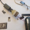
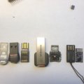
The test canidate card readers and testing method

IMG_0396.JPG IMG_0397.JPG IMG_0399.JPG

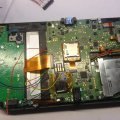
Once I found one that worked I had to start wiring it all up, and coat it all with a conformal coating of acrylic to prevent any possible shorting or arcing.

IMG_0400.JPG IMG_0401.JPG IMG_0406.JPG IMG_0409.JPG

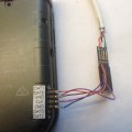
Afterwards I closed it all up and these are the results. The little switch is used to put it into booterror mode so it can be read.

IMG_0420.JPG IMG_0421.JPG IMG_0417.JPG

And finally the booterror screen when the switch is on and it normally running when it is off. It is using all 4 DAT lines and this is just a USB 2.0 reader so about 18MB/s isn't bad. Also fun to note, after I connected it I popped the battery out and it remained on which the charging light. I assume this is because it's not actually doing anything due to the system fault.

IMG_0418.JPG IMG_0426.JPG Win32Read.JPG

Soo all in all it was a fun little day project, the hardest part of it all? making the micro USB adapter to 1.27mm pitch adapter because my method of making PCBs needs a better print quality. In the end, after about 3 boards and minor changes, it all works. :lol: The only annoying issue is that you cannot charge and play with a standard USB port from a computer as it keeps trying to access the internal eMMC and lags the system A LOT. This could be very easily solved by adding another switch to disconnect and even pull down the data lines of the usb plug for usb charge mode.
 

kelroy

Well-Known Member
Newcomer
Joined
Jan 10, 2015
Messages
61
Trophies
0
Age
32
XP
80
Country
Avalynn what was the exactly microsd reader you use?. I got the kingston one, if it works i gonna test it this week-end.
 

Site & Scene News

Popular threads in this forum

General chit-chat
Help Users
  • No one is chatting at the moment.
    Psionic Roshambo @ Psionic Roshambo: By the power of Florida Man, I have the power!!! *Lifts up meth pipe* Meth Man!!! lol