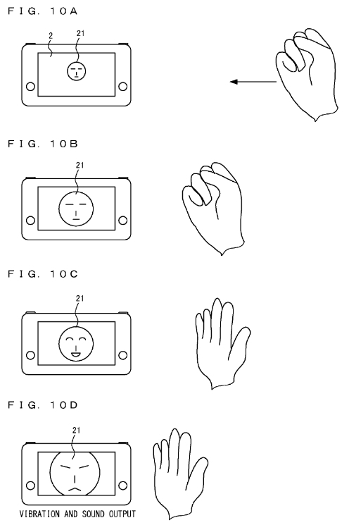
FIGS. 10A to 10D are each a diagram showing an example of a process based on a gesture input using the infrared camera 4. As shown in FIG. 10A, when the user makes their right hand into “rock” at a predetermined position in the right side surface direction of the portable electronic apparatus 1 while holding the portable electronic apparatus 1 with their left hand, a character 21 is displayed on the display 2. As shown in FIG. 10B, when, from the state of FIG. 10A, the user moves their right hand toward the right side surface of the portable electronic apparatus 1 while their right hand is kept as “rock”, the character 21 displayed on the display 2 is enlarged.
Furthermore, when, from the state shown in FIG. 10B, the user makes their right hand into “paper”, the facial expression of the character 21 on the display 2 changes (FIG. 10C). For example, as shown in FIG. 10C, the character 21 changes to have a smile expression. Moreover, as shown in FIG. 10D, when the user moves their right hand toward the portable electronic apparatus 1 while their right hand is kept as “paper”, the displayed character 21 is further enlarged, and the facial expression of the character 21 changes. At that time, the vibrator 11 may operate to vibrate the portable electronic apparatus 1, and a sound may be outputted from the speaker 13.
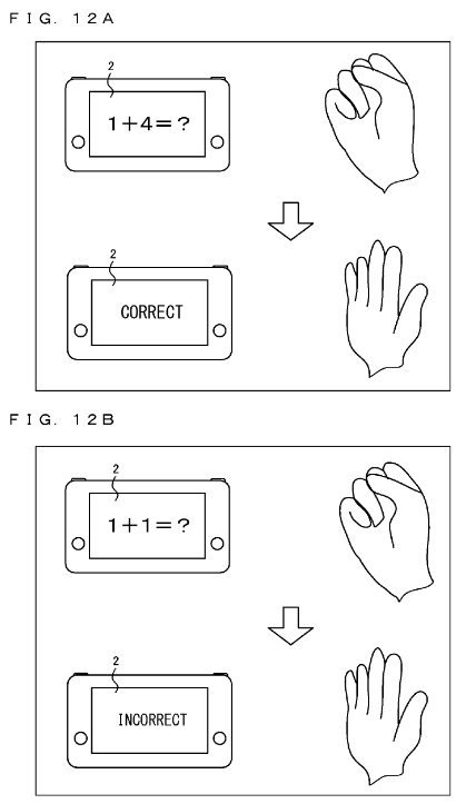
FIGS. 12A and 12B are each a diagram showing another example of a process based on a gesture input using the infrared camera 4. In this example, a calculation question is displayed on the display 2. The user answers the question displayed on the display 2, by using their right hand. For example, when a character string “1+4=?” is displayed as shown in FIG. 12A, if the user performs, by using their right hand, a gesture input (a gesture of “paper”) indicating “5” which is the correct answer of this question, a display indicating that the answer is correct is performed on the display 2. At that time, a sound indicating that the answer is correct may be outputted, or the vibrator 11 may be operated in a pattern indicating that the answer is correct, to vibrate the portable electronic apparatus 1.
When a character string “1+1=?” is displayed as shown in FIG. 12B, if the user performs, by using their right hand, a gesture input (an input of “5” by a gesture) different from the correct answer of this question, a display indicating the answer is incorrect is performed on the display 2. At that time, a sound indicating that the answer is incorrect may be outputted, or the vibrator 11 may be operated in a pattern indicating that the answer is incorrect.

Next, an example of a process using the distance measuring sensor 5 will be described. FIG. 13 is a diagram showing the example of the process using the distance measuring sensor 5. As shown in FIG. 13, when the user puts their right hand at a predetermined position in the right side surface direction of the portable electronic apparatus 1 while holding the portable electronic apparatus 1 with their left hand, a snake character 22 appears from the right edge of the display 2. When the user moves their right hand toward the portable electronic apparatus 1, the snake character 22 extends leftward from the right edge of the display 2. Specifically, the portable electronic apparatus 1 calculates the distance between the portable electronic apparatus 1 and the right hand of the user on the basis of information from the distance measuring sensor 5, and sets a length of the snake character 22 in accordance with the calculated distance. Then, the portable electronic apparatus 1 displays the snake character 22 on the display 2. In addition, depending on the distance, the portable electronic apparatus 1 may operate the vibrator 11 to vibrate the portable electronic apparatus 1.
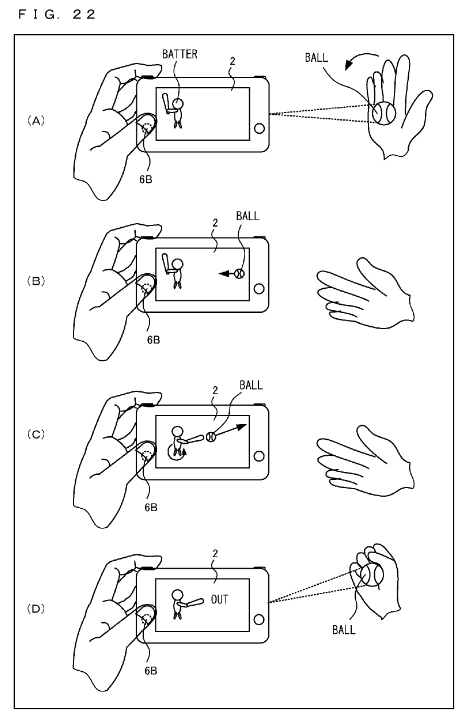
As shown in (A) of FIG. 22, a batter is displayed on the display 2. When the user makes a gesture of “paper” with their right hand, the portable electronic apparatus 1 recognizes the gesture on the basis of an image from the infrared camera 4, and projects an image of a ball onto the right hand of the user by using the projector 8. Next, when the user makes a gesture of swinging their right hand, the image of the ball projected on the right hand of the user disappears, and the ball appears from the right edge of the display 2 and moves in the leftward direction of the screen ((B) of FIG. 22). When the user presses the input button 6B at the timing at which the ball reaches a predetermined range of the batter, the batter hits back the ball ((C) of FIG. 22). The hit-back ball moves in the rightward direction of the screen. The user makes a gesture of “rock” at predetermined timing (timing at which the hit-back ball reaches the right hand) after the ball reaches the right edge of the display 2. Accordingly, an image of the ball is projected onto the right hand of the user as if the user caught the hit-back ball ((D) of FIG. 22). At that time, characters “OUT” indicating that the user is successful in catching the ball may be displayed on the display 2, and a sound may be outputted, or the portable electronic apparatus 1 may vibrate. The portable electronic apparatus 1 may recognize the position of the right hand of the user (a position on a plane parallel to the right side surface of the portable electronic apparatus, and/or a position in a direction perpendicular to the right side surface) on the basis of an image from the infrared camera 4 or a distance measured by the distance measuring sensor 5, and may project an image of the ball onto the right hand of the user in accordance with a result of the recognition. When the user does not make a gesture of “rock” at the above-described predetermined timing or the timing at which the gesture of “rock” is made deviates from the above-described predetermined timing, the user fails in catching the ball, and the image of the ball as shown in (D) of FIG. 22 is not projected onto the right hand. For example, an image different from the ball may be projected onto the right hand, or characters “ERROR” or “HIT” may be displayed on the display 2. When a gesture made by the user cannot be recognized with the infrared camera 4, the same process as described above may be performed by detecting movement of the hand with the distance measuring sensor 5

For example, when an attachment including an operation section (hereinafter referred to as an "extension controller") is attached to the right controller 4, the main unit 2 can detect an operation performed on the operation section based on the image-capturing results from the infrared image-capturing section 123. Therefore, the main unit 2 can execute an information process in accordance with an operation performed on the operation section by using the image-capturing results.
Specifically, the extension controller can be attached to and detached from the right controller 4, and include buttons and a movable operation section such as a stick, for example. The extension controller includes, inside the housing, a movable portion that moves (herein, the movement includes rotation) in response to an operation performed on an operation section. For example, the movable portion is a member configured to move in response to a button, which is an operation section, being pressed down. Here, the extension controller is attached to the right controller 4 so that the infrared image-capturing section 123 can capture an image of the movable portion inside the housing. For example, the housing of the extension controller is provided with a window portion, and the infrared image-capturing section 123 can capture an image of the movable portion via the window portion, with the extension controller attached to the right controller 4. Then, the main unit 2 can identify an operation performed on an operation section of the extension controller based on the position and/or the attitude of the movable portion in the image captured by the infrared image-capturing section 123. Thus, by using captured images, the main unit 2 may execute an information process in response to an operation performed on the operation section.