Gaming GBA no power

Soulboogie

Member
OP
Newcomer
Joined
Apr 7, 2021
Messages
9
Trophies
0
Age
37
XP
66
Country
United States
I guess bad corrosion is common on these GBAs? This is my second bad board out of 4. The last one had a bad CPU. I'd like to save this one if I can.

Did the typical and cleaned up as much corrosion as I could, checked the fuse, and repaired the faulty power switch.

I am getting 3V out of the switch.

I have a working board I am using as reference, can anyone help explain why I am getting these discrepancies:

Motherboard.jpg


Close up of both Transistors.jpg

Transistor 5

Left leg = 3V - normal
Upper right leg = 0V - normal
Lower right leg = 0V - abnormal (should be 0.5V)

Transistor above C43

Left left = 3V - abnormal (should be 6V)

I've replaced Q5 with a spare and it still gave the same results. I seem to lose all power after that transistor but I haven't thoroughly checked everything. Be nice to get some expert advice since I'm new at this.
 
Last edited by Soulboogie,

Soulboogie

Member
OP
Newcomer
Joined
Apr 7, 2021
Messages
9
Trophies
0
Age
37
XP
66
Country
United States
The battery solder pad looks toast, the power switch looks toast, and have you checked the F1 fuse?

Yeah the fuse is good, and getting power too Q5. I lose it there. I'm getting weak power in the transistor next to it. Would bad CAPs do something similar?

Are you buying things stored in a shed by a humid seaside?
Buying online, and getting junk.
 

Soulboogie

Member
OP
Newcomer
Joined
Apr 7, 2021
Messages
9
Trophies
0
Age
37
XP
66
Country
United States
Replaced the CAPs, no change. It's very frustrating to see where the voltage drops but have no idea why.

I need a crash course on transistors, the faulty board's transistors' continuity doesn't match the working motherboard. Also my testing don't reflect what I've seen online.

I assume transistors have continuity one way or the other, never both ways. But on both boards I'm getting continuity both ways. But the resistance between the faulty and working transistors don't match (I assume that's the issue, but why).

I need to swap a know working transistor over to the faulty board, or figure out how to test transistors.
I'll need to buy another board because this working one is someone else's and I don't wanna damage it.

Any tips on transistor? A good video to watch? I'd like to eliminate this discrepancy before I continue.
 
Last edited by Soulboogie,

Soulboogie

Member
OP
Newcomer
Joined
Apr 7, 2021
Messages
9
Trophies
0
Age
37
XP
66
Country
United States
I was about to go to bed, but it was bothering me. I found out why my readings were inconsistent. When the Transistor is in circuit the continuity changes depending on the power switch's position. The working board has a loose power switch, which was throwing me curve balls all last night. So after a few videos on transistors and with testing both boards on the same switch position I was able to figure a few things out.

Searching online I found that Q5's part number is FDV303N. Which I can get off of Digikey. But more importantly FDV303N is used at least twice on a GBA board. Q4 Shares the same part number. I tested Q4 on the faulty board and got the same results as the working board. That means Q5 should yield the same continuity, yet it isn't. (Continuity is different and I have continuity on pins that shouldn't)

Which could mean I replace a faulty transistor with another faulty transistor lol. The spare came off the board with a faulty CPU. And just to satisfy my curiosity I decided the test that boards Q4, it was also bad. I have a feeling a good portion of transistors are blown on this bad CPU board. Lesson learned; check the part before swapping!

I'm going to order a few FDV303N off of digikey and I'll post the result after swapping it in.
 

Soulboogie

Member
OP
Newcomer
Joined
Apr 7, 2021
Messages
9
Trophies
0
Age
37
XP
66
Country
United States
Q5 was definitely bad but the system still isn't booting. Still not getting power on the bottom right leg of Q5 (needs to be 3v).

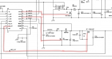
I've done more volt chasing and I'm at the limit of my knowledge. I've been using a schematic and I would appreciate a little help. I need to know how the power flows, what gets power first. For example, I can't tell if the power is lost before or after Q5.

Also noticed I don't have voltage on a few pins on U4. I'll upload a image of what ones. (Screenshot _####)

No power on VDRV5, VDRV3, REG_EXT.

I've also replaced U4 and T1 with spares and no change.

I hope this isn't another multiple fault board. Please lend me a hand, I'm at a complete loss.
 

Attachments

  • GBA-service-Manual page18.pdf
    8.3 MB · Views: 133
  • Screenshot_20210507-024200.png
    Screenshot_20210507-024200.png
    427.6 KB · Views: 191

Site & Scene News

Popular threads in this forum

General chit-chat
Help Users
  • No one is chatting at the moment.
    SylverReZ @ SylverReZ: https://www.youtube.com/watch?v=uLN9qrJ8ESs