I installed everything and double checked for shorts or any other damage, but everything seems fine. However when i turn on my console it just boots up normaly. No LED indicators except a bleak green and red lights. I'm pretty sure it's something to do with the firmware cause im using Seeed RP2040. Tried reflashing it, but after reflashing i get bleak green and red light. Am i supposed to bridge the RGB connectors and if so where are they on the SEEEDs board?
You are using an out of date browser. It may not display this or other websites correctly.
You should upgrade or use an alternative browser.
You should upgrade or use an alternative browser.
Picofly AIO Thread
- Thread starter Adran_Marit
- Start date
- Views 526,134
- Replies 3,360
- Likes 60

Did you bridge the "detection" jumper for the Seed RP2040 as indicated in the guide? This way FW will know that you got this board, and not RP2040-Zero.I installed everything and double checked for shorts or any other damage, but everything seems fine. However when i turn on my console it just boots up normaly. No LED indicators except a bleak green and red lights. I'm pretty sure it's something to do with the firmware cause im using Seeed RP2040. Tried reflashing it, but after reflashing i get bleak green and red light. Am i supposed to bridge the RGB connectors and if so where are they on the SEEEDs board?

- Joined
- Sep 2, 2020
- Messages
- 1,288
- Trophies
- 0
- Age
- 39
- Location
- TORONTO
- Website
- form.jotform.com
- XP
- 2,222
- Country

You dont need to do anything on the RBG LED but you bridge detection pinsI installed everything and double checked for shorts or any other damage, but everything seems fine. However when i turn on my console it just boots up normaly. No LED indicators except a bleak green and red lights. I'm pretty sure it's something to do with the firmware cause im using Seeed RP2040. Tried reflashing it, but after reflashing i get bleak green and red light. Am i supposed to bridge the RGB connectors and if so where are they on the SEEEDs board?

Quick question before I commit to desolder the "extras". The instructions says to remove the buttons, USB socket and 3.3v regulator after flashing the FW on the pico. I believe this is done for clearance (besides the regulator perhaps), so my question is, can those be left on until the installation is confirmed working in case there are FW issues and the chip needs to be reflashed?

only unintall them after u know everything is workingQuick question before I commit to desolder the "extras". The instructions says to remove the buttons, USB socket and 3.3v regulator after flashing the FW on the pico. I believe this is done for clearance (besides the regulator perhaps), so my question is, can those be left on until the installation is confirmed working in case there are FW issues and the chip needs to be reflashed?
I'm glad that is the case, but I wonder now what's the point of removing the regulator at all. It's not like it'll help with any clearance like the buttons and the socket will. Unless I'm missing something.only unintall them after u know everything is working

Actually, the regulator is the tallest part on the bottom of the chip and will give you a little extra clearance.
It's also pointless once the USB port is removed, since the chip is supplied with 3.3V directly already.
It's also pointless once the USB port is removed, since the chip is supplied with 3.3V directly already.
it sure does otherwise we wouldnt remove it , plus on the other hand we dont need it anyways sinde we can boot with pico_toolboxI'm glad that is the case, but I wonder now what's the point of removing the regulator at all. It's not like it'll help with any clearance like the buttons and the socket will. Unless I'm missing something.

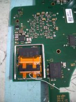
what do you mean alignment is not good? do i move it forward? left or right(facing from the left)? does that white line need to disappear under the chip?That, or shitty connection. What are the readings on other points: CMD, CLK?
Pico is clearly giving you a DAT0 related error.
I'm giving you as well this image:
View attachment 367237
That alignment is not good, you do the math.

what do you mean alignment is not good? do i move it forward? left or right(facing from the left)? does that white line need to disappear under the chip?
He meant when you look at the red and green arrow you can see the alignment is off.
cmd 492 clk 788That, or shitty connection. What are the readings on other points: CMD, CLK?
Pico is clearly giving you a DAT0 related error.
I'm giving you as well this image:
View attachment 367237
That alignment is not good, you do the math.
Post automatically merged:
you the white line should be perpendicular or align with the edge of the chip?He meant when you look at the red and green arrow you can see the alignment is off.
cmd 492 clk 788
Post automatically merged:
you the white line should be perpendicular or align with the edge of the chip?
It is not straight.
Exactly, the white line needs to be aligned with the eMMC, it should not go under the chip though (check my install below, the adapter is not the same, though you get the idea).
For re-aligning, you need to desolder both anchors, re-align everything and take a reading to ser if it changed.
When satisfied, just press the adapter gently under the chip with tweezers and solder the anchors. Take another reading.

For re-aligning, you need to desolder both anchors, re-align everything and take a reading to ser if it changed.
When satisfied, just press the adapter gently under the chip with tweezers and solder the anchors. Take another reading.
can you give me advice how to move the dat0 adapter? current reading is 798
Post automatically merged:
what reading should i get in my multimeter? im confused with it since its giving me whole number rather than decimals...Exactly, the white line needs to be aligned with the eMMC, it should not go under the chip though (check my install below, the adapter is not the same, though you get the idea).
For re-aligning, you need to desolder both anchors, re-align everything and take a reading to ser if it changed.
When satisfied, just press the adapter gently under the chip with tweezers and solder the anchors. Take another reading.View attachment 367315
Attachments
I have another multimeter that displays the whole number, 798 is the same as 0.798V.can you give me advice how to move the dat0 adapter? current reading is 798
Post automatically merged:
what reading should i get in my multimeter? im confused with it since its giving me whole number rather than decimals...
With the red probe on the GND and the black on the DAT0 point, you should get from 0.4 to 0.6 V. First re-align the adapter, it's not good yet.
does v1 lite and oled have the same dat0 value in multimeter? maybe i could compare my oled with my lite and v1 dat0 values...thank you for all the tips so far will work on it later...I have another multimeter that displays the whole number, 798 is the same as 0.798V.
With the red probe on the GND and the black on the DAT0 point, you should get from 0.4 to 0.6 V. First re-align the adapter, it's not good yet.

No. 2.67 is the latest. The "Important Posts" in the other thread has this link to the latest firmware.Last pico firmware is 2.66 uf?????
https://gbatemp.net/threads/picofly-a-hwfly-switch-modchip.622701/post-10090767
The pdf uf2 files?????No. 2.67 is the latest. The "Important Posts" in the other thread has this link to the latest firmware.
https://gbatemp.net/threads/picofly-a-hwfly-switch-modchip.622701/post-10090767
Yes. Just remove the ".pdf" extension after you download the files. They are really binary files but ".pdf" is added as a workaround so the files can be attached to the post. Note that the author of that post is the developer of the hack so it is the latest and greatest.The pdf uf2 files?????
Similar threads
- Replies
- 8
- Views
- 1K
- Replies
- 8
- Views
- 3K
- Replies
- 3
- Views
- 688
- Replies
- 10
- Views
- 2K
- Replies
- 1
- Views
- 2K
Site & Scene News
New Hot Discussed
-
-
25K views
Nintendo Switch firmware update 18.0.1 has been released
A new Nintendo Switch firmware update is here. System software version 18.0.1 has been released. This update offers the typical stability features as all other... -
19K views
The first retro emulator hits Apple's App Store, but you should probably avoid it
With Apple having recently updated their guidelines for the App Store, iOS users have been left to speculate on specific wording and whether retro emulators as we... -
19K views
Delta emulator now available on the App Store for iOS
The time has finally come, and after many, many years (if not decades) of Apple users having to side load emulator apps into their iOS devices through unofficial...by ShadowOne333 96 -
19K views
TheFloW releases new PPPwn kernel exploit for PS4, works on firmware 11.00
TheFlow has done it again--a new kernel exploit has been released for PlayStation 4 consoles. This latest exploit is called PPPwn, and works on PlayStation 4 systems... -
16K views
Nintendo takes down Gmod content from Steam's Workshop
Nintendo might just as well be a law firm more than a videogame company at this point in time, since they have yet again issued their now almost trademarked usual...by ShadowOne333 121 -
16K views
Nintendo officially confirms Switch successor console, announces Nintendo Direct for next month
While rumors had been floating about rampantly as to the future plans of Nintendo, the President of the company, Shuntaro Furukawa, made a brief statement confirming... -
14K views
A prototype of the original "The Legend of Zelda" for NES has been found and preserved
Another video game prototype has been found and preserved, and this time, it's none other than the game that spawned an entire franchise beloved by many, the very...by ShadowOne333 31 -
12K views
Anbernic reveals specs details of pocket-sized RG28XX retro handheld
Anbernic is back with yet another retro handheld device. The upcoming RG28XX is another console sporting the quad-core H700 chip of the company's recent RG35XX 2024... -
11K views
Name the Switch successor: what should Nintendo call its new console?
Nintendo has officially announced that a successor to the beloved Switch console is on the horizon. As we eagerly anticipate what innovations this new device will... -
11K views
Nintendo Switch Online adds two more Nintendo 64 titles to its classic library
Two classic titles join the Nintendo Switch Online Expansion Pack game lineup. Available starting April 24th will be the motorcycle racing game Extreme G and another...
-
-
-
238 replies
Name the Switch successor: what should Nintendo call its new console?
Nintendo has officially announced that a successor to the beloved Switch console is on the horizon. As we eagerly anticipate what innovations this new device will...by Costello -
208 replies
Nintendo officially confirms Switch successor console, announces Nintendo Direct for next month
While rumors had been floating about rampantly as to the future plans of Nintendo, the President of the company, Shuntaro Furukawa, made a brief statement confirming...by Chary -
121 replies
Nintendo takes down Gmod content from Steam's Workshop
Nintendo might just as well be a law firm more than a videogame company at this point in time, since they have yet again issued their now almost trademarked usual...by ShadowOne333 -
97 replies
The first retro emulator hits Apple's App Store, but you should probably avoid it
With Apple having recently updated their guidelines for the App Store, iOS users have been left to speculate on specific wording and whether retro emulators as we...by Scarlet -
96 replies
Delta emulator now available on the App Store for iOS
The time has finally come, and after many, many years (if not decades) of Apple users having to side load emulator apps into their iOS devices through unofficial...by ShadowOne333 -
82 replies
Nintendo Switch firmware update 18.0.1 has been released
A new Nintendo Switch firmware update is here. System software version 18.0.1 has been released. This update offers the typical stability features as all other...by Chary -
80 replies
TheFloW releases new PPPwn kernel exploit for PS4, works on firmware 11.00
TheFlow has done it again--a new kernel exploit has been released for PlayStation 4 consoles. This latest exploit is called PPPwn, and works on PlayStation 4 systems...by Chary -
74 replies
New static recompiler tool N64Recomp aims to seamlessly modernize N64 games
As each year passes, retro games become harder and harder to play, as the physical media begins to fall apart and becomes more difficult and expensive to obtain. The...by Chary -
74 replies
"Nintendo World Championships: NES Edition", a new NES Remix-like game, launching July 18th
After rumour got out about an upcoming NES Edition release for the famed Nintendo World Championships, Nintendo has officially unveiled the new game, titled "Nintendo...by ShadowOne333 -
71 replies
DOOM has been ported to the retro game console in Persona 5 Royal
DOOM is well-known for being ported to basically every device with some kind of input, and that list now includes the old retro game console in Persona 5 Royal...by relauby
-