


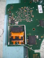
I installed everything and double checked for shorts or any other damage, but everything seems fine. However when i turn on my console it just boots up normaly. No LED indicators except a bleak green and red lights. I'm pretty sure it's something to do with the firmware cause im using Seeed RP2040. Tried reflashing it, but after reflashing i get bleak green and red light. Am i supposed to bridge the RGB connectors and if so where are they on the SEEEDs board?
Picofly AIO Thread
- Thread starter Adran_Marit
- Start date
- Views 534,843
- Replies 3,369
- Likes 60


Similar threads
-
-
-
-
-
-
 @
Psionic Roshambo:
I think Game streaming should work like this.... Local Hardware able the run the game fine, game engine and common assets stored locally, all FMV and music and textures could be streaming+1
@
Psionic Roshambo:
I think Game streaming should work like this.... Local Hardware able the run the game fine, game engine and common assets stored locally, all FMV and music and textures could be streaming+1 -
-
 @
Xdqwerty:
also @BigOnYa im making some progress on my gdevelop project, implemented various mechanics
@
Xdqwerty:
also @BigOnYa im making some progress on my gdevelop project, implemented various mechanics -
-
 @
BigOnYa:
Or free government supplied high speed internet be nice also. Like Obama care. Xdqwerty that's cool, its time consuming but rewarding once done or playable, to see what you've made from scratch. Animations take forever, but worth it.+1
@
BigOnYa:
Or free government supplied high speed internet be nice also. Like Obama care. Xdqwerty that's cool, its time consuming but rewarding once done or playable, to see what you've made from scratch. Animations take forever, but worth it.+1 -
-
-
@
Xdqwerty:
@BigOnYa,+1
and the visual aspect of the game is quite crude (the sprite that looks best is that of the protagonist just because he is a stickman with sunglasses) -
@
BigOnYa:
There is a bullets behaviour you assign to your character, that makes the code easier, under "behaviours"
-
-
@
Xdqwerty:
i meant that when the character is pointing to the right, the bullets spawn where they should, but when he is on the right, they move to the right but the spawn point is incorrect
-
@
BigOnYa:
Itch.io has lots of free assets also. Under the bullets behavior tab, there is a "rotate bullets" option, can try that. Or in the code can try
- fire bullet Player.X(PlayerDirection) -
-
-
@
BigOnYa:
That's cool tho, I'm proud of you going back to it, not giving up. It is difficult at first to learn, but fun once you get the hang of it. I think I've watched every tutorial video there is, but I still struggle sometimes to get stuff to work right. But gotta keep trying dif things, and eventually you will get it right.+1
-
-
-
-
-
 them
them