- Joined
- Sep 2, 2020
- Messages
- 1,293
- Trophies
- 0
- Age
- 39
- Location
- TORONTO
- Website
- form.jotform.com
- XP
- 2,229
- Country

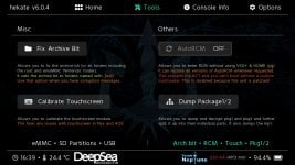
YES, it works.(HEKATE 6.0.4)Hi, does the 2.67 can work with official boot with hekate ?
reboot > OFW
Cause i stay on screen off, stock (sysnand) work, Thanks
Just did 16.0.2 to 16.0.3 update via wifi on OFW w/ v2.67 on pico