

Hardware Tutorial
Updated
MLC2SD - A Wii U NAND (eMMC) Replacement Interposer
Hi all,
I designed a little Interposer which allows for a clean replacement of the eMMC chip in the Wii U with an SD card: https://github.com/jan-hofmeier/mlc2sd
The Wii U has 2 NAND Chips, the SLC and the eMMC, this targets the eMMC only. Since the Wii U actually uses a SD controller to talk to the eMMC and Nintendo didn't nerf the driver, the eMMC can be replaced 1:1 with an SD card by just passivly connecting it.
The eMMC is also called MLC. In this post I will use the term eMMC to refer to the Hardware Chip and MLC to the logical thing the Wii U OS sees and the data contained on it. For example the MLC can be cloned from the eMMC to a SD card.

The main purpose is to help people experiencing the "There is a Problem with the system memory" Error Code 160-0103, caused by NAND Corruption. Keep in mind that if that error occurs during bootup it could also be a CBHC brick. To determine the cause I recommend checking out the Ultimate Wii U Troubleshooting Guide.
But it could also be used to give your Wii U a Internal Memory upgrade.
For details on how to use this to fix or upgrade your internal Memory and also limitations of this method check out this guide: How To: Upgrading / Rebuilding Wii U Internal Memory (MLC)
There is also the option to clone the (broken) MLC to a same size SD card, and fix the corruption afterwards: Repair a broken eMMC but rebuilding is usally the prefered way to fix corruption.
If you can't solder and don't want to learn it, this probably isn't the solution for you, but we still got you covered: Fixing system memory error 160-0103 (failing eMMC) without soldering | using redNAND with ISFShax
Over just connecting the pins of the SD slot with the pads on the board, I looked after a few other things, which can become useful:
READ: Doing the Hardware work is only half of the work. For the Wii U to work the MLC need to have some data. Depending on the Guilde you are following you need to make sure to first install ISFShax or clone the old MLC, before doing any Hardware work, or you might not have a way to setup the MLC on the SD card.
Don't solder the SD slot or the capacitor, before the Guide tells you, else you won't be able to reach some solder joints!
I generally try to avoid leaded solder, but since the GND plane of the Wii U sucks so much heat away, it really helps here, with anything related to the GND connection.
You really need to take your time with the GND connection, it really sucks the heat away and getting the solder to flow will take time.
You find the gerber files on the release page of the github project, so you can order some at the PCB Manufacturer for your choice: https://github.com/jan-hofmeier/mlc2sd/releases
I also put it up as a PCBWay project: https://www.pcbway.com/project/shareproject/MLC2SD_A_Wii_U_eMMC_replacement_413cebe0.html (for transperacy, if you order through the project, I will get some money from PCBWay. It doesn't have any adavantages or disadvantages for you as far as I am aware. But really feel free to order wherever is convinient for you).
When ordering make sure to select castellated holes and a thickness of 0.6mm or 0.8mm (you have to do this even if you order through the project)
Since it doesn't make sense for everyone to order their own, since the base cost is relativly high compared to the piece price, it makes sense to ask in the forum if someone else already has some or to form a group and order together. At the moment I am aware of that @V10lator has some.
Yes, you can and it will work. That's what we did in the beginning. You fnd the pinouts online. If you do that I recommend using magnet wire. In my opinion the Interposer just is a cleaner, more professional looking, easier to solder solution, but choice is yours.
Probably not. If your Wii U works well now, it probably isn't affected by the problem. Especially if you have a Samsung or Toshiba eMMC, you shouldn't worry. I also don't suggest getting one just in case you might need it later. It's easy enough to make some on demand and in an emergency you can fix it without the interposer using some magnet wires and an SD adapter.
I designed a little Interposer which allows for a clean replacement of the eMMC chip in the Wii U with an SD card: https://github.com/jan-hofmeier/mlc2sd
The Wii U has 2 NAND Chips, the SLC and the eMMC, this targets the eMMC only. Since the Wii U actually uses a SD controller to talk to the eMMC and Nintendo didn't nerf the driver, the eMMC can be replaced 1:1 with an SD card by just passivly connecting it.
The eMMC is also called MLC. In this post I will use the term eMMC to refer to the Hardware Chip and MLC to the logical thing the Wii U OS sees and the data contained on it. For example the MLC can be cloned from the eMMC to a SD card.
Who is this for?
The main purpose is to help people experiencing the "There is a Problem with the system memory" Error Code 160-0103, caused by NAND Corruption. Keep in mind that if that error occurs during bootup it could also be a CBHC brick. To determine the cause I recommend checking out the Ultimate Wii U Troubleshooting Guide.
But it could also be used to give your Wii U a Internal Memory upgrade.
For details on how to use this to fix or upgrade your internal Memory and also limitations of this method check out this guide: How To: Upgrading / Rebuilding Wii U Internal Memory (MLC)
There is also the option to clone the (broken) MLC to a same size SD card, and fix the corruption afterwards: Repair a broken eMMC but rebuilding is usally the prefered way to fix corruption.
If you can't solder and don't want to learn it, this probably isn't the solution for you, but we still got you covered: Fixing system memory error 160-0103 (failing eMMC) without soldering | using redNAND with ISFShax
Features
Over just connecting the pins of the SD slot with the pads on the board, I looked after a few other things, which can become useful:
- Exposing all signals on big Pads, including SCLK - This allows dumping of a eMMC, in case the console no longer boots. Also the the side of the clock comming from the System which gets connected to the SD is exposed for debugging purposes.
- Castellatd holes are connected at the bottom - Since the castelated vias are somewhat fragile and can breake, I made sure to connect the trace at the bottom, where you solder. so even if the castellated via breaks, it should still make a good connection.
- All routing (except for the castelated via connection) is on the top - This reduces the likelyhood for shorts from scrateched solder mask, also it makes tracing the traces easier when debugging.
- Removed GND fill - On this Interposer a GND fill won't help with signal integrity and might even hurt it. Also it made soldering harder, since it sucks heat, so I mostly removed it. I only kept a little GND area around the SD slot pads, to help with mechanical stability
- Big GND VIA - Allows the use of a thicker tip to make sure the solder propery melts
- All design files are availible on github, so you can adapt the design to your needs: https://github.com/jan-hofmeier/mlc2sd
- Placement of the 3V3 pad to stay away from the shield
What you need
- MLC2SD Interposer
- SD slot (make sure the footpint matches)
- 10µF ceramic capacior
- Flux
- Solder wick
- Wire for (3V3)
- scalpel or an x-acto knife
- Solder (leaded helps a lot here)
- Soldering Iron
How to solder
READ: Doing the Hardware work is only half of the work. For the Wii U to work the MLC need to have some data. Depending on the Guilde you are following you need to make sure to first install ISFShax or clone the old MLC, before doing any Hardware work, or you might not have a way to setup the MLC on the SD card.
Don't solder the SD slot or the capacitor, before the Guide tells you, else you won't be able to reach some solder joints!
I generally try to avoid leaded solder, but since the GND plane of the Wii U sucks so much heat away, it really helps here, with anything related to the GND connection.
You really need to take your time with the GND connection, it really sucks the heat away and getting the solder to flow will take time.
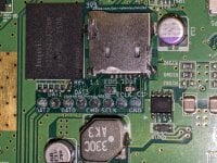
- Cut the CLK line (R26) - using a scalpel or an x-acto knife - to disable the eMMC. Be carefull, you don't want to accidentally cut into layers below or traces next to it. Cut away from the other traces towards the GND plane. After cutting check with a multimeter if it is really cut and neither side is shorted to GND.
- Remove C655 (if populated). Add fresh solder on both sides and then heat both sides alternating until you can slide it of. You probably have to crank the heat of the iron all the way up since the GND plane will be sucking a lot of heat. Preheating the board areah (even with a hairdryer) will help.
- Clean the pads of C655 by first adding fresh solder and then use the solder wick with flux and wick the solder away, so the pads are flat.
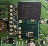
- Check the Alignment of the MLC2SD: It should lay flat and if you press it against the Hynix eMMC, the castellated VIAs should line out with the resistors and the big GND VIA should overlap with the GND pad of C655.
- Solder the GND connection: Use lots of heat and enough flux to solder the big GND VIA to the GND pad of the Wii U board. Make sure the solder flows good and the connection to the pad is good. Take care of the alignment, don't move the MLC2SD after you removed the Iron (while the solder is still molten) or it will make a weak joint. Once it is cooled, check of the joint really holds by tryoing to move the MLC2SD. If this joint breaks after soldering the SD slot, you have a problem, so take your time to make sure it is good.
Also make sure the top is flat, since the SD slot will be put on top of it, you can't have solder sticking up. Flux helps and wick to to remove access solder. Ceck if the slot lays flat. - Solder the castellated VIAs to the resistors / pads. Use a multimeter to check for shorts on neighbouring pins and shorts to GND
- Solder the SD slot. First make sure it is in the alignment holes. Then first solder the 4 structural joins around it (while making sure the pins are aligned with the pads) and then soldering the pins. Make sure none of the pins are shorted together. Flux helps in clearing bridges.
- Solder the ceramic capacitor. I remommend preparing one pad with solder, then add flux and solder one side of the cap to it. Then solder the other side of the cap while adding solder.
- Solder the 3V3 connection using a wire to the transistor leg on the board.
- If you don't need to hardware dump the eMMC, close the EDIS jumper with a solder blob
How to get one
You find the gerber files on the release page of the github project, so you can order some at the PCB Manufacturer for your choice: https://github.com/jan-hofmeier/mlc2sd/releases
I also put it up as a PCBWay project: https://www.pcbway.com/project/shareproject/MLC2SD_A_Wii_U_eMMC_replacement_413cebe0.html (for transperacy, if you order through the project, I will get some money from PCBWay. It doesn't have any adavantages or disadvantages for you as far as I am aware. But really feel free to order wherever is convinient for you).
When ordering make sure to select castellated holes and a thickness of 0.6mm or 0.8mm (you have to do this even if you order through the project)
Since it doesn't make sense for everyone to order their own, since the base cost is relativly high compared to the piece price, it makes sense to ask in the forum if someone else already has some or to form a group and order together. At the moment I am aware of that @V10lator has some.
But can't I just wire up a SD slot or a micro SD adapter without an Interposer?
Yes, you can and it will work. That's what we did in the beginning. You fnd the pinouts online. If you do that I recommend using magnet wire. In my opinion the Interposer just is a cleaner, more professional looking, easier to solder solution, but choice is yours.
I don't have problems, should I still get one for preventetive maintance?
Probably not. If your Wii U works well now, it probably isn't affected by the problem. Especially if you have a Samsung or Toshiba eMMC, you shouldn't worry. I also don't suggest getting one just in case you might need it later. It's easy enough to make some on demand and in an emergency you can fix it without the interposer using some magnet wires and an SD adapter.
Attachments
Last edited by SDIO,


