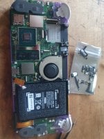
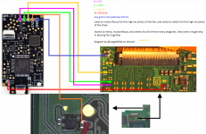
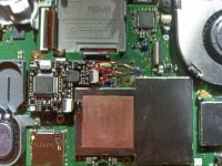
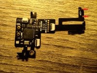
Hacking Switch lite Hwfly wiring.

School4Ants

Member
OP
Newcomer
Joined
Dec 7, 2020
Messages
7
Trophies
0
Age
40
XP
80
Country
New Zealand
Hey all, I have a hwfly v4.2 lite chip was wanting to skip the 3.3v flex cable as its a bit poorly designed, is there a wiring guide out there to manually wire that particular flex with points on the board and chip? Thanks heaps.
 

Attachments

  • 20230105_203410.jpg
    20230105_203410.jpg
    1.6 MB · Views: 99

SylverReZ

The planet is fine. The people are crazy.
Member
Joined
Sep 13, 2022
Messages
7,310
Trophies
3
Location
The Wired
Website
m4x1mumrez87.neocities.org
XP
22,531
Country
United Kingdom
Hey all, I have a hwfly v4.2 lite chip was wanting to skip the 3.3v flex cable as its a bit poorly designed, is there a wiring guide out there to manually wire that particular flex with points on the board and chip? Thanks heaps.
Found this

hwfly-lite-v4-2-install-diagram-got-it-from-an-aliexpress-v0-xc0mciwzkjw91.png
 
  • Love
Reactions: impeeza

School4Ants

Member
OP
Newcomer
Joined
Dec 7, 2020
Messages
7
Trophies
0
Age
40
XP
80
Country
New Zealand

Nagaa

Well-Known Member
Newcomer
Joined
Nov 8, 2020
Messages
98
Trophies
0
XP
765
Country
France
Here you have diagram for hwfly lite and the switch lite pin out

But you should use the flex cable, just pre tin the different point on your switch lite before soldering the flex
 

Attachments

  • hwfly_oled2lite.png
    hwfly_oled2lite.png
    602.5 KB · Views: 99
  • OLED-DIAGRAM-TYPE-A.jpg
    6.8 MB · Views: 145

xldon2lx

Active Member
Newcomer
Joined
Nov 20, 2022
Messages
37
Trophies
0
Age
35
XP
114
Country
Philippines
Guys, he's clearly asking for a diagram of wiring the "hwfly/sx lite" to his switch lite and not the "hwfly OLED" modchip yet you keep giving him diagrams of hwfly OLED.

@School4Ants

Just message sthetix directly on twitter or youtube. I don't think there exists any yet for now.
 
Last edited by xldon2lx,
  • Like
Reactions: School4Ants

School4Ants

Member
OP
Newcomer
Joined
Dec 7, 2020
Messages
7
Trophies
0
Age
40
XP
80
Country
New Zealand
Guys, he's clearly asking for a diagram of wiring the "sx lite" to his switch lite and not the "hwfly OLED" modchip yet you keep giving him diagrams of hwfly OLED.

@School4Ants

Just message sthetix directly on twitter or youtube. I don't think there exists any yet for now.
Cheers bro, I may have caused confusion with my wording. I'll see if they have anything.
 

xldon2lx

Active Member
Newcomer
Joined
Nov 20, 2022
Messages
37
Trophies
0
Age
35
XP
114
Country
Philippines
Cheers bro, I may have caused confusion with my wording. I'll see if they have anything.
No bro it was my wording that's wrong. It's suppose to be really called hwfly lite and not sx lite but I got confused since sx lite is what I have and they're visually the same.
 

Nagaa

Well-Known Member
Newcomer
Joined
Nov 8, 2020
Messages
98
Trophies
0
XP
765
Country
France
Guys, he's clearly asking for a diagram of wiring the "hwfly/sx lite" to his switch lite and not the "hwfly OLED" modchip yet you keep giving him diagrams of hwfly OLED.

@School4Ants

Just message sthetix directly on twitter or youtube. I don't think there exists any yet for now.
With the 2 picture i send there is all point to do the wiring on a HWFLY Lite, just need to use your brain...
 
  • Haha
Reactions: impeeza

mundaka0x

Member
Newcomer
Joined
Jul 7, 2017
Messages
5
Trophies
0
Age
32
XP
65
Country
Mexico
Hey all, I have a hwfly v4.2 lite chip was wanting to skip the 3.3v flex cable as its a bit poorly designed, is there a wiring guide out there to manually wire that particular flex with points on the board and chip? Thanks heaps.
Post automatically merged:

found it on aliexpress but its blurry. ive been wrapping my head around these pinouts for days now
 

Attachments

  • -1106251461-783578312 (1).jpg
    -1106251461-783578312 (1).jpg
    191.7 KB · Views: 94

whisky9

Well-Known Member
Newcomer
Joined
Aug 20, 2020
Messages
76
Trophies
0
XP
564
Country
Vietnam
E14ACF01-00AA-4DBD-9A4F-1F5C5E4D4FF9.jpeg


The White mark is 3.3V and the Pink mark is GND. I've just googled it.
Post automatically merged:

Look at my reply above, you have all to do it
You sent him misinformation pic. The chip in your pic is v4.1 or older which has 3.3V point at the bottom to solder; OP's chip is v4.2 it has no 3.3V at the bottom that's why he asked for a diagram.
1FBF2AFC-920E-4ABF-ABDB-4C1E12A95F23.jpeg
441277A4-132D-4CEB-93DC-CBAC11DBCA31.jpeg
 
Last edited by whisky9,
  • Love
Reactions: impeeza

Nagaa

Well-Known Member
Newcomer
Joined
Nov 8, 2020
Messages
98
Trophies
0
XP
765
Country
France
Oh okey, never seen this chip but if everything is coming from the flex pcb cable it's pretty easy to track the pin out on the chip
 

jenots

New Member
Newbie
Joined
May 31, 2022
Messages
4
Trophies
0
Age
35
Location
Riga
XP
74
Country
Latvia
Hi. Just want to be sure that my aliexpress, presumably v4.2(?), chip is working before soldering. Went through all pinouts and all seems fine, but could'n find pin to check for these two. Are they necessary, as of few posts above is pic with one of them crossed out? Or is it enough witch A,B,C,D, 3.3V and GND?
 

Attachments

  • IMG_20231027_190552.jpg
    IMG_20231027_190552.jpg
    1,006.3 KB · Views: 26

Site & Scene News

Popular threads in this forum

General chit-chat
Help Users
    BigOnYa @ BigOnYa: After watching, that I feel like I'm on them already +1