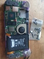
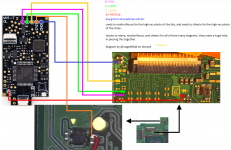
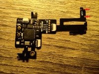
That was the first place I tried but couldn't find any thread with a diagram of the wiring points on the chip.Search function at top of the site, you can find several threads about it.
Found thisHey all, I have a hwfly v4.2 lite chip was wanting to skip the 3.3v flex cable as its a bit poorly designed, is there a wiring guide out there to manually wire that particular flex with points on the board and chip? Thanks heaps.
That was the first place I tried but couldn't find any thread with a diagram of the wiring points on the chip.
Cheers, I have that, what I'm after is a diagram to wire the 3.3v flex so I don't have to use it as it doesn't line up particularly well.
Thanks for that, but it doesn't have a lite diagram for that flex, just the various wiring for oleds.
Cheers bro, I may have caused confusion with my wording. I'll see if they have anything.Guys, he's clearly asking for a diagram of wiring the "sx lite" to his switch lite and not the "hwfly OLED" modchip yet you keep giving him diagrams of hwfly OLED.
@School4Ants
Just message sthetix directly on twitter or youtube. I don't think there exists any yet for now.
No bro it was my wording that's wrong. It's suppose to be really called hwfly lite and not sx lite but I got confused since sx lite is what I have and they're visually the same.Cheers bro, I may have caused confusion with my wording. I'll see if they have anything.
With the 2 picture i send there is all point to do the wiring on a HWFLY Lite, just need to use your brain...Guys, he's clearly asking for a diagram of wiring the "hwfly/sx lite" to his switch lite and not the "hwfly OLED" modchip yet you keep giving him diagrams of hwfly OLED.
@School4Ants
Just message sthetix directly on twitter or youtube. I don't think there exists any yet for now.
Hey all, I have a hwfly v4.2 lite chip was wanting to skip the 3.3v flex cable as its a bit poorly designed, is there a wiring guide out there to manually wire that particular flex with points on the board and chip? Thanks heaps.
Look at my reply above, you have all to do itPost automatically merged:
found it on aliexpress but its blurry. ive been wrapping my head around these pinouts for days now
You sent him misinformation pic. The chip in your pic is v4.1 or older which has 3.3V point at the bottom to solder; OP's chip is v4.2 it has no 3.3V at the bottom that's why he asked for a diagram.Look at my reply above, you have all to do it