

You are using an out of date browser. It may not display this or other websites correctly.
You should upgrade or use an alternative browser.
You should upgrade or use an alternative browser.
Staff Posts
Recent threadmarks
sharing files
Important Posts
Recent threadmarks
Firmwares


I've been reading through the modchip source code, and I am by no means a veteran embedded engineer, so naturally it is a bit of a puzzle to me. I stumbled upon the `mariko_bct.h` file inside the repository, and I am struggling to figure out what it means. I know bct stands for boot configuration table, and mariko is the codename for the v2 switch. However, what are the buffers defined inside this header file? Did rehius define them themselves, or did they find them elsewhere? I presume this code is injected whenever the glitch succeeds and sets up the boot configuration to load the custom bootloader?

My problem was thin wires on the CLK, after this information I managed to solve it, for the CLK it can't be thin wires!

Has anyone bought pico chips and had them not flash a green light when dropping the file onto them? I have three here. I’m not sure if it’s the chip itself or maybe the led. I bought 30 of them.
- Joined
- Sep 2, 2020
- Messages
- 1,286
- Trophies
- 0
- Age
- 39
- Location
- TORONTO
- Website
- form.jotform.com
- XP
- 2,222
- Country

Has anyone bought pico chips and had them not flash a green light when dropping the file onto them? I have three here. I’m not sure if it’s the chip itself or maybe the led. I bought 30 of them.
Just make sure you have ** code and you should be good
Last edited by jkyoho,
What do you mean by ** code?same here,I got tiny from waveshare official site and they came with RGB test code out of box. Nuke them and put v2.75 fw on it but no success flash after that. Howevevr, I do have ** code when replugin to PC without holding boot button after fw flashed. So they are good to bang on.
Just make sure you have ** code and you should be good
- Joined
- Sep 2, 2020
- Messages
- 1,286
- Trophies
- 0
- Age
- 39
- Location
- TORONTO
- Website
- form.jotform.com
- XP
- 2,222
- Country

Duh2x short pulse yellow led
https://gbatemp.net/posts/10090767/
 I’ll plug them back in and see what happens
I believe he just copy from spacecraft-nxI've been reading through the modchip source code, and I am by no means a veteran embedded engineer, so naturally it is a bit of a puzzle to me. I stumbled upon the `mariko_bct.h` file inside the repository, and I am struggling to figure out what it means. I know bct stands for boot configuration table, and mariko is the codename for the v2 switch. However, what are the buffers defined inside this header file? Did rehius define them themselves, or did they find them elsewhere? I presume this code is injected whenever the glitch succeeds and sets up the boot configuration to load the custom bootloader?
https://github.com/Spacecraft-NX/firmware/blob/master/firmware/src/mariko_bct.h

your solder points are good. no, your 3.3v would not have touched the shield because i do more than 40 oleds now with bridging 2 caps and the blob is bigger than yours but no problem. rst when connected is 1.3 and 0 when disconnecting are normal. not sure what caused your problem to be like this but i had 2 cases maybe it will be a reference for you. 1 was that i used clone hwfly rp2040 the console worked but when turned off i couldn't launch the console anymore (black screen) but my in my case i could boot into hekate, after 2 days putting it aside it booted nomrally again. the 2nd one was that i used rp2040-zero it gave the code of emmc cmd1 block, i tried everything for an hour but turned out it was the chip being faulty. hope it help you somehow.As I said I removed the emmc adapter, I only have pictures of CPU flex, 3.3V, A and D. B is disconnected and C is also disconnected. I have no training video but it totally worked the first time before reassembly. This is bizarre.
Post automatically merged:
I did try with all wires off the modchip, you mean I should disconnect all wires from the board too? Will that make a difference...?
Post automatically merged:
Sorry I meant to also reply here.
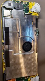
That’s a neat way to do it. Do you still cut the shield?It fits perfect here (close to the speaker), just make sure everything is insulated because the shield goes very close to the edge of rp2040 on this position.
I took this picture before covering everything in kapton so again, make sure you don't short something

I didn't have to cut anything at all. Buttons, regulator and USB port were removed, of course.That’s a neat way to do it. Do you still cut the shield?

No, but as I said, you need to be careful as it is really a tight fit and the solder points are right below the rp2040 so make sure you use 38/40awg preferably single core as it makes everything easier. And you need to make sure you route those red wires on the yellow or green path (see pic) because the way they are placed on the picture does not work. This takes quite some time so if you are doing alot of these (which i'm not) maybe trimming the rp2040 (as suggested above) is not a bad idea.That’s a neat way to do it. Do you still cut the shield?
Attachments
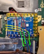
Thank you, my case is looking awfully similar to your first one with the exception of the Hekate boot, it's also looking awfully similar to a tvpartsworld video I'll link but I don't have a USB power meter and my max chip doesn't get hot when connecting the battery, have not tried usb cable yet in fear of damaging it.your solder points are good. no, your 3.3v would not have touched the shield because i do more than 40 oleds now with bridging 2 caps and the blob is bigger than yours but no problem. rst when connected is 1.3 and 0 when disconnecting are normal. not sure what caused your problem to be like this but i had 2 cases maybe it will be a reference for you. 1 was that i used clone hwfly rp2040 the console worked but when turned off i couldn't launch the console anymore (black screen) but my in my case i could boot into hekate, after 2 days putting it aside it booted nomrally again. the 2nd one was that i used rp2040-zero it gave the code of emmc cmd1 block, i tried everything for an hour but turned out it was the chip being faulty. hope it help you somehow.
What I hate the most is that it might have been the chip or something, which is a clone... Doubt I actually did something wrong, my soldering looks spot on at least in my eyes and I've seen way more botched installations on this very thread that worked perfectly!
I ordered the MAX77812EWB+T chip off mouser just in case I guess because I can't think of anything else that'd be at fault here. Is it worth getting a proper hwfly or instinct chip to see if it "revives" my switch? I've seen that happen on some skhynix oleds in some forum posts.
It doesn't look like it to me, although probably providing a similar purpose, the mariko bct used in picofly's repository differs from the spacecraft one. Furthermore, the picofly provides some kind of key which is presumably used by the bootrom to verify the contents of the bct data, effectively spoofing it. That's my interpretation of it anywayI believe he just copy from spacecraft-nx


Thank you, my case is looking awfully similar to your first one with the exception of the Hekate boot, it's also looking awfully similar to a tvpartsworld video I'll link but I don't have a USB power meter and my max chip doesn't get hot when connecting the battery, have not tried usb cable yet in fear of damaging it.
What I hate the most is that it might have been the chip or something, which is a clone... Doubt I actually did something wrong, my soldering looks spot on at least in my eyes and I've seen way more botched installations on this very thread that worked perfectly!
I ordered the MAX77812EWB+T chip off mouser just in case I guess because I can't think of anything else that'd be at fault here. Is it worth getting a proper hwfly or instinct chip to see if it "revives" my switch? I've seen that happen on some skhynix oleds in some forum posts.
If your problem is a burned component, installing another modchip will not help you. In terms of debugging, HWFLY has more capability than Picofly.

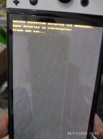
I had a problem I've never seen on this OLED. installation completed successfully, eMMC created, everything ok. the next day I turn it on and I have graphic artifacts and continuous freezes. by moving the wires a little it resumes but I have a Blue screen in the original and a yellow screen already created in the eMMC. I solve it with an unbrick level 1. what could be the cause?
The installation is perfect, I'm experienced enough to say, all the values were in the norm in fact the first day it worked perfectly. I also changed modchips no improvement. Now it works perfectly.
The installation is perfect, I'm experienced enough to say, all the values were in the norm in fact the first day it worked perfectly. I also changed modchips no improvement. Now it works perfectly.
Attachments
Last edited by LuigiGad,
Had this a while ago (hwfly chip). Still don't know for sure what the cause was but maybe you could try and do as I did and hopefully it works for you too.I had a problem I've never seen on this OLED. installation completed successfully, eMMC created, everything ok. the next day I turn it on and I have graphic artifacts and continuous freezes. by moving the wires a little it resumes but I have a Blue screen in the original and a yellow screen already created in the eMMC. I solve it with an unbrick level 1. what could be the cause?
The installation is perfect, I'm experienced enough to say, all the values were in the norm in fact the first day it worked perfectly. I also changed modchips no improvement. Now it works perfectly.
https://gbatemp.net/threads/help-weird-oled-issue-after-chip-installation.630850/
When you backup your emmc, you got file BOOT0 that is the bct partition.It doesn't look like it to me, although probably providing a similar purpose, the mariko bct used in picofly's repository differs from the spacecraft one. Furthermore, the picofly provides some kind of key which is presumably used by the bootrom to verify the contents of the bct data, effectively spoofing it. That's my interpretation of it anyway
Spcecraft extract the whole bct into the header file.
https://github.com/Spacecraft-NX/firmware/blob/master/firmware/src/mariko_bct.h
Picofly used part of it.
https://github.com/rehius/usk/blob/main/mariko_bct.h
Then generate the whole bct in prepare_mariko_bct() such that it become like in the spacecraft table.
https://github.com/rehius/usk/blob/6530fd9fe58980ea03d47905bad5e871b9439b7a/payload.c#L700C6-L700C26
Maybe this is to reduce the size.
Basically both use the same binary.
This is the reference:
https://switchbrew.org/wiki/BCT
the sign part is the 0x0220-0x320 (RsaPssSig)
and the data is from the encrypted part 0x0480-end (RandomAesBlock-end)
Post automatically merged:
What method you use on the Dat0?I had a problem I've never seen on this OLED. installation completed successfully, eMMC created, everything ok. the next day I turn it on and I have graphic artifacts and continuous freezes. by moving the wires a little it resumes but I have a Blue screen in the original and a yellow screen already created in the eMMC. I solve it with an unbrick level 1. what could be the cause?
The installation is perfect, I'm experienced enough to say, all the values were in the norm in fact the first day it worked perfectly. I also changed modchips no improvement. Now it works perfectly.
Last edited by abal1000x,
Similar threads
- Replies
- 3
- Views
- 1K
- Replies
- 2
- Views
- 458
- Replies
- 42
- Views
- 6K
Site & Scene News
New Hot Discussed
-
-
24K views
Nintendo Switch firmware update 18.0.1 has been released
A new Nintendo Switch firmware update is here. System software version 18.0.1 has been released. This update offers the typical stability features as all other... -
19K views
The first retro emulator hits Apple's App Store, but you should probably avoid it
With Apple having recently updated their guidelines for the App Store, iOS users have been left to speculate on specific wording and whether retro emulators as we... -
18K views
Delta emulator now available on the App Store for iOS
The time has finally come, and after many, many years (if not decades) of Apple users having to side load emulator apps into their iOS devices through unofficial...by ShadowOne333 96 -
18K views
TheFloW releases new PPPwn kernel exploit for PS4, works on firmware 11.00
TheFlow has done it again--a new kernel exploit has been released for PlayStation 4 consoles. This latest exploit is called PPPwn, and works on PlayStation 4 systems... -
16K views
Nintendo takes down Gmod content from Steam's Workshop
Nintendo might just as well be a law firm more than a videogame company at this point in time, since they have yet again issued their now almost trademarked usual...by ShadowOne333 120 -
15K views
Nintendo officially confirms Switch successor console, announces Nintendo Direct for next month
While rumors had been floating about rampantly as to the future plans of Nintendo, the President of the company, Shuntaro Furukawa, made a brief statement confirming... -
14K views
A prototype of the original "The Legend of Zelda" for NES has been found and preserved
Another video game prototype has been found and preserved, and this time, it's none other than the game that spawned an entire franchise beloved by many, the very...by ShadowOne333 31 -
12K views
Anbernic reveals specs details of pocket-sized RG28XX retro handheld
Anbernic is back with yet another retro handheld device. The upcoming RG28XX is another console sporting the quad-core H700 chip of the company's recent RG35XX 2024... -
11K views
Nintendo Switch Online adds two more Nintendo 64 titles to its classic library
Two classic titles join the Nintendo Switch Online Expansion Pack game lineup. Available starting April 24th will be the motorcycle racing game Extreme G and another... -
11K views
Name the Switch successor: what should Nintendo call its new console?
Nintendo has officially announced that a successor to the beloved Switch console is on the horizon. As we eagerly anticipate what innovations this new device will...
-
-
-
234 replies
Name the Switch successor: what should Nintendo call its new console?
Nintendo has officially announced that a successor to the beloved Switch console is on the horizon. As we eagerly anticipate what innovations this new device will...by Costello -
205 replies
Nintendo officially confirms Switch successor console, announces Nintendo Direct for next month
While rumors had been floating about rampantly as to the future plans of Nintendo, the President of the company, Shuntaro Furukawa, made a brief statement confirming...by Chary -
120 replies
Nintendo takes down Gmod content from Steam's Workshop
Nintendo might just as well be a law firm more than a videogame company at this point in time, since they have yet again issued their now almost trademarked usual...by ShadowOne333 -
97 replies
The first retro emulator hits Apple's App Store, but you should probably avoid it
With Apple having recently updated their guidelines for the App Store, iOS users have been left to speculate on specific wording and whether retro emulators as we...by Scarlet -
96 replies
Delta emulator now available on the App Store for iOS
The time has finally come, and after many, many years (if not decades) of Apple users having to side load emulator apps into their iOS devices through unofficial...by ShadowOne333 -
82 replies
Nintendo Switch firmware update 18.0.1 has been released
A new Nintendo Switch firmware update is here. System software version 18.0.1 has been released. This update offers the typical stability features as all other...by Chary -
80 replies
TheFloW releases new PPPwn kernel exploit for PS4, works on firmware 11.00
TheFlow has done it again--a new kernel exploit has been released for PlayStation 4 consoles. This latest exploit is called PPPwn, and works on PlayStation 4 systems...by Chary -
74 replies
"Nintendo World Championships: NES Edition", a new NES Remix-like game, launching July 18th
After rumour got out about an upcoming NES Edition release for the famed Nintendo World Championships, Nintendo has officially unveiled the new game, titled "Nintendo...by ShadowOne333 -
71 replies
DOOM has been ported to the retro game console in Persona 5 Royal
DOOM is well-known for being ported to basically every device with some kind of input, and that list now includes the old retro game console in Persona 5 Royal...by relauby -
64 replies
Microsoft is closing down several gaming studios, including Tango Gameworks and Arkane Austin
The number of layoffs and cuts in the videogame industry sadly continue to grow, with the latest huge layoffs coming from Microsoft, due to what MIcrosoft calls a...by ShadowOne333
-