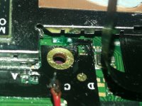
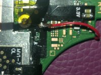
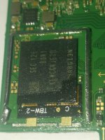
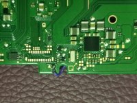
Hi everyone, I lost the five pads and I measured it all on a new OLED Motherboard but it did not show any value. however, when I connected the LCD cable and measured it again and it did show value. Are all the pads have no connection or sth else? thanks
You are using an out of date browser. It may not display this or other websites correctly.
You should upgrade or use an alternative browser.
You should upgrade or use an alternative browser.
Staff Posts
Recent threadmarks
sharing files
Important Posts
Recent threadmarks
Firmwares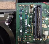

Hi @rehius , I wanted to express my gratitude for the incredible effort you put into creating this mod. Thanks to your mod, I was able to sell some modded switches and generate enough money to purchase a new MacBook Pro and Sony Xperia 1 V. I am truly thankful to you for enabling me to achieve all of this. Once again, thank you so much, bro!
- Joined
- Sep 2, 2020
- Messages
- 1,280
- Trophies
- 0
- Age
- 39
- Location
- TORONTO
- Website
- form.jotform.com
- XP
- 2,210
- Country

measure them in resistance mode,Hi everyone, I lost the five pads and I measured it all on a new OLED Motherboard but it did not show any value. however, when I connected the LCD cable and measured it again and it did show value. Are all the pads have no connection or sth else? thanks
they should be no connection. Put on new fpc connector and good to go
Post automatically merged:
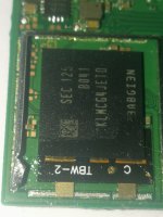
good luck reballing Apu and emmcThank you @Dee87 and @abal1000x for your valuable inputs, I do have a green adaptor that I bought and will use on this. This is going to be an exciting challenge. I no longer see any reason to get frustrated when killing a console, I learn and enjoy.
@rehius that's 10 now")
Last edited by jkyoho,


- Joined
- Jan 22, 2014
- Messages
- 248
- Trophies
- 1
- Age
- 40
- Location
- Cape Town, Western Cape
- XP
- 1,810
- Country

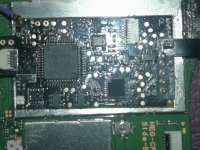
Post pics of install and also which switchAfter installing hwfly boot chip end boot to red light and nex try boot same red light now console not boot. ****
Post automatically merged:
What is your diode reading for DAT 0?Hi !!
I hack my second Oled and it work fine but now it boot on official and i have this error "=* D0 is not connected"
I see my DT0 and its ok, but i have always this error...

Thank you @Dee87 and @abal1000x for your valuable inputs, I do have a green adaptor that I bought and will use on this. This is going to be an exciting challenge. I no longer see any reason to get frustrated when killing a console, I learn and enjoy.
@rehius that's 10 now
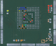
YSK that the green adapters have pretty bad quality on the preapplied solder balls and it may have to be reballed (on both sides) before using. On about half the adapters in the latest batch I bought, the balls were so uneven in size that some of them did not connect properly. Make sure to measure all important points after attaching the adapter, before attaching emmc. (vddi, vcc, vccq, dat0-7, ds, clk, cmd, gnd)
Thank you for this. I got the diagram ready and planning to go fully surgical on this task. Wish me luck.YSK that the green adapters have pretty bad quality on the preapplied solder balls and it may have to be reballed (on both sides) before using. On about half the adapters in the latest batch I bought, the balls were so uneven in size that some of them did not connect properly. Make sure to measure all important points after attaching the adapter, before attaching emmc. (vddi, vcc, vccq, dat0-7, ds, clk, cmd, gnd)
Attachments
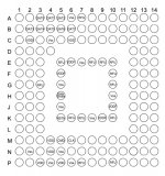

Thank you for this. I got the diagram ready and planning to go fully surgical on this task. Wish me luck.
some of those aren't connected to anything and the naming in your diagram is a bit odd. use this one instead
Attachments
I desolder B and C im lost.Post pics of install and also which switch
Post automatically merged:
What is your diode reading for DAT 0?
Attachments
-
 IMG_20230717_195437.jpg2.2 MB · Views: 27
 -
 IMG_20230717_194824.jpg3 MB · Views: 22
 -
 IMG_20230717_194837.jpg2.4 MB · Views: 19
 -
 IMG_20230717_194839.jpg2.4 MB · Views: 18
 -
 IMG_20230717_194914.jpg1.8 MB · Views: 17
 -
 IMG_20230717_195012.jpg1.5 MB · Views: 23
 -
 IMG_20230717_024427.jpg2.2 MB · Views: 23
 -
 IMG_20230717_024432.jpg2.4 MB · Views: 20
 -
 IMG_20230717_194649.jpg3.6 MB · Views: 24
 -
 IMG_20230717_194709.jpg3.1 MB · Views: 19
 -
 IMG_20230717_194753.jpg2.6 MB · Views: 22
 -
 IMG_20230717_195012.jpg1.5 MB · Views: 22
 -
 IMG_20230717_203353.jpg2.7 MB · Views: 27
Last edited by Danook28,
- Joined
- Sep 2, 2020
- Messages
- 1,280
- Trophies
- 0
- Age
- 39
- Location
- TORONTO
- Website
- form.jotform.com
- XP
- 2,210
- Country
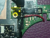
Where did you solder B on HWFLY?I desolder B and C im lost.
This pic after desolder.. I soldering B point on B...Where did you solder B on HWFLY?View attachment 383802
- Joined
- Sep 2, 2020
- Messages
- 1,280
- Trophies
- 0
- Age
- 39
- Location
- TORONTO
- Website
- form.jotform.com
- XP
- 2,210
- Country
what's your purple cable diode reading at that situation? More like you desolder/solder B cable to a ground point IMOThis pic after desolder.. I soldering B point on B...
- Joined
- Jan 22, 2014
- Messages
- 248
- Trophies
- 1
- Age
- 40
- Location
- Cape Town, Western Cape
- XP
- 1,810
- Country
diode readings for all points - ps personally i don't like the flexesI desolder B and C im lost.
what's your purple cable diode reading at that situation? More like you desolder/solder B cable to a ground point IMO
I never soldring B point to ground. You want me to read B? It was two try boot but end to red light. Now not booting at all.
Post automatically merged:
diode readings for all points - ps personally i don't like the flexes
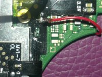
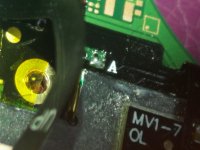
Multimater red on point and black on ground
Dat0 is 0.675 v
CLK is D point 0.502 v
A Point is 0.670 v
3v3 point is 0.805
B point is 0 if read red on ground and black on point is 0.414v
Ground point is 0
Last edited by Danook28,

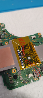
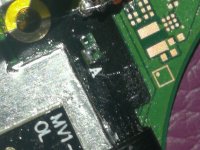
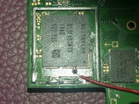
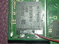
Hi Guys. Go easy on your boy, but I messed up on this OLED big time. I kept getting *== and I would grind the CLK more and more to hopefully get a glitch going but instead, I ended up with this: (VIEWERS DISCRETION ADVISED):
Looking at the bright side, I've always wanted to learn how to work with emmc, I'll just give it a go and see if I could solder CLK directly into it.
Notes:
I still get 0.6v on multimeter when I point it on the trace right beneath the APU (tried soldering there, no luck)
I've changed the pico and re-wired the whole thing.
For new comers:
THIS IS INSTALLER's fault.
Jesus, this is what I end up with.... ready to be soldered to.
I would say to the bad modders that you should be treating each console as your own.
A bit of respect


Post automatically merged:
or something to offer you a beer, cofee or chicha...
This is it... how do we repay him?
I'm more of a beginner modder. I don't leave my clients dry. I reimburse them with Amazon Gift cards so they can buy whatever color of their model.Jesus, this is what I end up with.... ready to be soldered to.
I would say to the bad modders that you should be treating each console as your own.
A bit of respect
Post automatically merged:
This is it... how do we repay him?
Post automatically merged:
Thanks brot
Thanks brother, always helpful <3some of those aren't connected to anything and the naming in your diagram is a bit odd. use this one instead
- Joined
- Jan 22, 2014
- Messages
- 248
- Trophies
- 1
- Age
- 40
- Location
- Cape Town, Western Cape
- XP
- 1,810
- Country
clk is a tad low and b should be around 2.9vI never soldring B point to ground. You want me to read B? It was two try boot but end to red light. Now not booting at all.
Post automatically merged:
Multimater red on point and black on ground
Dat0 is 0.675 v
CLK is D point 0.502 v
A Point is 0.670 v
3v3 point is 0.805
B point is 0 if read red on ground and black on point is 0.414v
Ground point is 0
That's a HWFLY modchip budWould this modchip belong to this thread?

If so, I'll ask mods to move one post of mine to here...
Similar threads
- Replies
- 3
- Views
- 1K
- Replies
- 2
- Views
- 304
- Replies
- 42
- Views
- 6K
Site & Scene News
New Hot Discussed
-
-
23K views
Wii U and 3DS online services shutting down today, but Pretendo is here to save the day
Today, April 8th, 2024, at 4PM PT, marks the day in which Nintendo permanently ends support for both the 3DS and the Wii U online services, which include co-op play...by ShadowOne333 179 -
16K views
Nintendo Switch firmware update 18.0.1 has been released
A new Nintendo Switch firmware update is here. System software version 18.0.1 has been released. This update offers the typical stability features as all other... -
16K views
The first retro emulator hits Apple's App Store, but you should probably avoid it
With Apple having recently updated their guidelines for the App Store, iOS users have been left to speculate on specific wording and whether retro emulators as we... -
15K views
Delta emulator now available on the App Store for iOS
The time has finally come, and after many, many years (if not decades) of Apple users having to side load emulator apps into their iOS devices through unofficial...by ShadowOne333 96 -
14K views
MisterFPGA has been updated to include an official release for its Nintendo 64 core
The highly popular and accurate FPGA hardware, MisterFGPA, has received today a brand new update with a long-awaited feature, or rather, a new core for hardcore...by ShadowOne333 54 -
10K views
Nintendo takes down Gmod content from Steam's Workshop
Nintendo might just as well be a law firm more than a videogame company at this point in time, since they have yet again issued their now almost trademarked usual...by ShadowOne333 113 -
9K views
A prototype of the original "The Legend of Zelda" for NES has been found and preserved
Another video game prototype has been found and preserved, and this time, it's none other than the game that spawned an entire franchise beloved by many, the very...by ShadowOne333 31 -
8K views
Nintendo "Indie World" stream announced for April 17th, 2024
Nintendo has recently announced through their social media accounts that a new Indie World stream will be airing tomorrow, scheduled for April 17th, 2024 at 7 a.m. PT...by ShadowOne333 53 -
8K views
Anbernic reveals specs details of pocket-sized RG28XX retro handheld
Anbernic is back with yet another retro handheld device. The upcoming RG28XX is another console sporting the quad-core H700 chip of the company's recent RG35XX 2024... -
8K views
"Famidash", a new fanmade demake for the NES of Geometry Dash
Homebrew games for retro consoles have seen a rise over the years thanks to new tools and community-made development kits, which help a lot in the process of creating...by ShadowOne333 23
-
-
-
179 replies
Wii U and 3DS online services shutting down today, but Pretendo is here to save the day
Today, April 8th, 2024, at 4PM PT, marks the day in which Nintendo permanently ends support for both the 3DS and the Wii U online services, which include co-op play...by ShadowOne333 -
113 replies
Nintendo takes down Gmod content from Steam's Workshop
Nintendo might just as well be a law firm more than a videogame company at this point in time, since they have yet again issued their now almost trademarked usual...by ShadowOne333 -
97 replies
The first retro emulator hits Apple's App Store, but you should probably avoid it
With Apple having recently updated their guidelines for the App Store, iOS users have been left to speculate on specific wording and whether retro emulators as we...by Scarlet -
96 replies
Delta emulator now available on the App Store for iOS
The time has finally come, and after many, many years (if not decades) of Apple users having to side load emulator apps into their iOS devices through unofficial...by ShadowOne333 -
77 replies
Nintendo Switch firmware update 18.0.1 has been released
A new Nintendo Switch firmware update is here. System software version 18.0.1 has been released. This update offers the typical stability features as all other...by Chary -
58 replies
TheFloW releases new PPPwn kernel exploit for PS4, works on firmware 11.00
TheFlow has done it again--a new kernel exploit has been released for PlayStation 4 consoles. This latest exploit is called PPPwn, and works on PlayStation 4 systems...by Chary -
55 replies
Nintendo Switch Online adds two more Nintendo 64 titles to its classic library
Two classic titles join the Nintendo Switch Online Expansion Pack game lineup. Available starting April 24th will be the motorcycle racing game Extreme G and another...by Chary -
54 replies
MisterFPGA has been updated to include an official release for its Nintendo 64 core
The highly popular and accurate FPGA hardware, MisterFGPA, has received today a brand new update with a long-awaited feature, or rather, a new core for hardcore...by ShadowOne333 -
53 replies
Nintendo "Indie World" stream announced for April 17th, 2024
Nintendo has recently announced through their social media accounts that a new Indie World stream will be airing tomorrow, scheduled for April 17th, 2024 at 7 a.m. PT...by ShadowOne333 -
52 replies
The FCC has voted to restore net neutrality, reversing ruling from 2017
In 2017, the United States Federal Communications Commission (FCC) repealed net neutrality. At the time, it was a major controversy between internet service providers...by Chary
-
Popular threads in this forum
General chit-chat
-
-
-
-
-
-
-
-
 @
BigOnYa:
Good deal. I love Sun chips. I also love Rye chips, and had to order some from Amazon cause can't find in stores much anymore.
@
BigOnYa:
Good deal. I love Sun chips. I also love Rye chips, and had to order some from Amazon cause can't find in stores much anymore. -
-
@
BigOnYa:
Is funny how they replaced the $5 foot long sub, with a 1" wide $5 foot long cookie or cinna stick, cheap asses
-
-
-
-
-
-
-
-
-
-
-
-
-
-
-