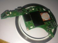
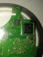
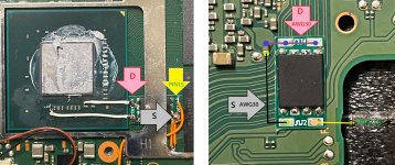
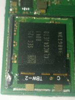
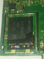
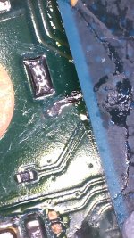
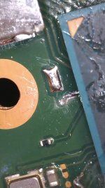
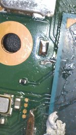
If you have a dat0 adapter, maybe you can use it to check your own dat0 line. connect it(but don't solder it) and check for continuity between the adapter and the end of your dat0 line, at the picofly joint. would that be possible? I am not familiar with dat0 reballs100% but my one starts!? OFW works no problem. Disconnected pico and boots into ofw. so must be a line that haven't soldered well. ill have to go back and see but im sure its the cmd line. might be bad solder joint even though it gives a good reading. very tricky. or emmc line wire not being hit to the correct dat0 point. maybe could have shifted to the dat1 point. Doubt it but don't want to go straight to that if i can help it. Do the small checks first and if all fails, back to reball again
You are using an out of date browser. It may not display this or other websites correctly.
You should upgrade or use an alternative browser.
You should upgrade or use an alternative browser.
Staff Posts
Recent threadmarks
sharing files
Important Posts
Recent threadmarks
Firmwaresdon't have one. but the line shows continuity. 620 reading in diode modeIf you have a dat0 adapter, maybe you can use it to check your own dat0 line. connect it(but don't solder it) and check for continuity between the adapter and the end of your dat0 line, at the picofly joint. would that be possible? I am not familiar with dat0 reballs
add a second mosfet and it will boot100% but my one starts!? OFW works no problem. Disconnected pico and boots into ofw. so must be a line that haven't soldered well. ill have to go back and see but im sure its the cmd line. might be bad solder joint even though it gives a good reading. very tricky. or emmc line wire not being hit to the correct dat0 point. maybe could have shifted to the dat1 point. Doubt it but don't want to go straight to that if i can help it. Do the small checks first and if all fails, back to reball again
Or try another pico board with 2.73fw. Who knows. Will try to be as methodical as possible so others will know whY to do better if they get stuck in my position.
the 3 oled i have tried the one mosfet on also would try to glitch very long.
when i added a second mosfet it worked flwless
Post automatically merged:
why should he have to check it when he set a Permanent dat0 Adapter,that makes no sense.If you have a dat0 adapter, maybe you can use it to check your own dat0 line. connect it(but don't solder it) and check for continuity between the adapter and the end of your dat0 line, at the picofly joint. would that be possible? I am not familiar with dat0 reballs
Because I was not familiar with how the permanent dat0 mod is done and I thought the dat0 was not connected properly(cold joint)add a second mosfet and it will boot
the 3 oled i have tried the one mosfet on also would try to glitch very long.
when i added a second mosfet it worked flwless
Post automatically merged:
why should he have to check it when he set a Permanent dat0 Adapter,that makes no sense.
Last edited by twins333,
Good Morning.
See images bellow.
Error code
*==
Post automatically merged:
Hello!
I forgot send a image of mosfet.
See image bellow.
Now the error changed.
Is ==* (long, long, small). CPU always reach BCT check. (No glitch reaction.
Wrong connection Capacitor
======================================================
suggestion
Use thick wire GND, VCC, PIN26, MOS-D, MOS-S
One side thin line PIN29,PIN28,PIN27,PIN15
BOOT card LOGO (OFW) strange phenomenon... Check PIN26
MOS-D, S are solidly welded and can indeed boot up stably
Attachments
i made the bridge but still i getting a green lightRed is good, green is bad. If green after flash, then solder jumper. Reflash, and LED should be good.
Post automatically merged:
i did the bridgde and still getting green lightRed is good, green is bad. If green after flash, then solder jumper. Reflash, and LED should be good.
it varies a lot but it can be an optionWrong connection Capacitor
======================================================
suggestion
Use thick wire GND, VCC, PIN26, MOS-D, MOS-S
One side thin line PIN29,PIN28,PIN27,PIN15
BOOT card LOGO (OFW) strange phenomenon... Check PIN26
MOS-D, S are solidly welded and can indeed boot up stably
There is no need for thicker wire then 0.1mm on oled with picofly , it makes no difference in anything. and beginners shouldnt use any thicker wire anyways all there gonne do with thicker wire is rip of padsWrong connection Capacitor
======================================================
suggestion
Use thick wire GND, VCC, PIN26, MOS-D, MOS-S
One side thin line PIN29,PIN28,PIN27,PIN15
BOOT card LOGO (OFW) strange phenomenon... Check PIN26
MOS-D, S are solidly welded and can indeed boot up stably
Post automatically merged:
there are completly different colors with the new firmware. we now have "morse code as issue discribtion "i made the bridge but still i getting a green light
Post automatically merged:
i did the bridgde and still getting green light
Hello.GND 3v3 wier type?????
I don't know the thickness but I took it from a cell phone charging cable.
َHello.
I don't know the thickness but I took it from a cell phone charging cable.
I see multimater read 0.675 is it fine????
Attachments
Sorry, I didn't understand your question, you get this value by measuring what?َ
I see multimater read 0.675 is it fine????
The dat0 point readSorry, I didn't understand your question, you get this value by measuring what?
....
How would I add it with this mod? Which way too orientate it round.add a second mosfet and it will boot
the 3 oled i have tried the one mosfet on also would try to glitch very long.
when i added a second mosfet it worked flwless
Post automatically merged:
why should he have to check it when he set a Permanent dat0 Adapter,that makes no
Please can share your opinion : about time cost, reliability, risk, difficulty when comparing with emmc reball?Second time more precise
Probably safer than the dat0 adapters ;DSecond time more precise
time: No idea, reliability: should be as good as the emmc reball. Hell might be safer since you don't touch the emmc.Please can share your opinion : about time cost, reliability, risk, difficulty when comparing with emmc reball?
risk, EXTREME. Difficulty? Very! You can go to far and damage other traces on the otherside of the board for example.
Hi Guys. Go easy on your boy, but I messed up on this OLED big time. I kept getting *== and I would grind the CLK more and more to hopefully get a glitch going but instead, I ended up with this: (VIEWERS DISCRETION ADVISED):
Looking at the bright side, I've always wanted to learn how to work with emmc, I'll just give it a go and see if I could solder CLK directly into it.
Notes:
I still get 0.6v on multimeter when I point it on the trace right beneath the APU (tried soldering there, no luck)
I've changed the pico and re-wired the whole thing.
For new comers:
THIS IS INSTALLER's fault.
Attachments
the *==, have you check the cmd pullup resistor on the switch mainboard ?Hi Guys. Go easy on your boy, but I messed up on this OLED big time. I kept getting *== and I would grind the CLK more and more to hopefully get a glitch going but instead, I ended up with this: (VIEWERS DISCRETION ADVISED):
Looking at the bright side, I've always wanted to learn how to work with emmc, I'll just give it a go and see if I could solder CLK directly into it.
Notes:
I still get 0.6v on multimeter when I point it on the trace right beneath the APU (tried soldering there, no luck)
I've changed the pico and re-wired the whole thing. I guess some OLEDs just like to act up.
Hi Ab,the *==, have you check the cmd pullup resistor on the switch mainboard ?
yes, It's 4.7k. I re-soldered it three times.
Thanks for your input. Any more diagnostics on you mind?
Sorry no other idea.Hi Ab,
yes, It's 4.7k. I re-soldered it three times.
Thanks for your input. Any more diagnostics on you mind?
Similar threads
- Replies
- 3
- Views
- 1K
- Replies
- 2
- Views
- 526
- Replies
- 42
- Views
- 6K
Site & Scene News
New Hot Discussed
-
-
28K views
Nintendo Switch firmware update 18.0.1 has been released
A new Nintendo Switch firmware update is here. System software version 18.0.1 has been released. This update offers the typical stability features as all other... -
21K views
Nintendo officially confirms Switch successor console, announces Nintendo Direct for next month
While rumors had been floating about rampantly as to the future plans of Nintendo, the President of the company, Shuntaro Furukawa, made a brief statement confirming... -
21K views
TheFloW releases new PPPwn kernel exploit for PS4, works on firmware 11.00
TheFlow has done it again--a new kernel exploit has been released for PlayStation 4 consoles. This latest exploit is called PPPwn, and works on PlayStation 4 systems... -
20K views
New static recompiler tool N64Recomp aims to seamlessly modernize N64 games
As each year passes, retro games become harder and harder to play, as the physical media begins to fall apart and becomes more difficult and expensive to obtain. The... -
20K views
Delta emulator now available on the App Store for iOS
The time has finally come, and after many, many years (if not decades) of Apple users having to side load emulator apps into their iOS devices through unofficial...by ShadowOne333 96 -
19K views
Nintendo takes down Gmod content from Steam's Workshop
Nintendo might just as well be a law firm more than a videogame company at this point in time, since they have yet again issued their now almost trademarked usual...by ShadowOne333 127 -
15K views
Name the Switch successor: what should Nintendo call its new console?
Nintendo has officially announced that a successor to the beloved Switch console is on the horizon. As we eagerly anticipate what innovations this new device will... -
15K views
A prototype of the original "The Legend of Zelda" for NES has been found and preserved
Another video game prototype has been found and preserved, and this time, it's none other than the game that spawned an entire franchise beloved by many, the very...by ShadowOne333 32 -
14K views
Anbernic reveals specs details of pocket-sized RG28XX retro handheld
Anbernic is back with yet another retro handheld device. The upcoming RG28XX is another console sporting the quad-core H700 chip of the company's recent RG35XX 2024... -
12K views
Nintendo Switch Online adds two more Nintendo 64 titles to its classic library
Two classic titles join the Nintendo Switch Online Expansion Pack game lineup. Available starting April 24th will be the motorcycle racing game Extreme G and another...
-
-
-
262 replies
Name the Switch successor: what should Nintendo call its new console?
Nintendo has officially announced that a successor to the beloved Switch console is on the horizon. As we eagerly anticipate what innovations this new device will...by Costello -
227 replies
Nintendo officially confirms Switch successor console, announces Nintendo Direct for next month
While rumors had been floating about rampantly as to the future plans of Nintendo, the President of the company, Shuntaro Furukawa, made a brief statement confirming...by Chary -
127 replies
Nintendo takes down Gmod content from Steam's Workshop
Nintendo might just as well be a law firm more than a videogame company at this point in time, since they have yet again issued their now almost trademarked usual...by ShadowOne333 -
117 replies
New static recompiler tool N64Recomp aims to seamlessly modernize N64 games
As each year passes, retro games become harder and harder to play, as the physical media begins to fall apart and becomes more difficult and expensive to obtain. The...by Chary -
96 replies
Delta emulator now available on the App Store for iOS
The time has finally come, and after many, many years (if not decades) of Apple users having to side load emulator apps into their iOS devices through unofficial...by ShadowOne333 -
82 replies
Nintendo Switch firmware update 18.0.1 has been released
A new Nintendo Switch firmware update is here. System software version 18.0.1 has been released. This update offers the typical stability features as all other...by Chary -
80 replies
TheFloW releases new PPPwn kernel exploit for PS4, works on firmware 11.00
TheFlow has done it again--a new kernel exploit has been released for PlayStation 4 consoles. This latest exploit is called PPPwn, and works on PlayStation 4 systems...by Chary -
78 replies
"Nintendo World Championships: NES Edition", a new NES Remix-like game, launching July 18th
After rumour got out about an upcoming NES Edition release for the famed Nintendo World Championships, Nintendo has officially unveiled the new game, titled "Nintendo...by ShadowOne333 -
71 replies
DOOM has been ported to the retro game console in Persona 5 Royal
DOOM is well-known for being ported to basically every device with some kind of input, and that list now includes the old retro game console in Persona 5 Royal...by relauby -
66 replies
Ubisoft reveals 'Assassin's Creed Shadows' which is set to launch later this year
Ubisoft has today officially revealed the next installment in the Assassin's Creed franchise: Assassin's Creed Shadows. This entry is set in late Sengoku-era Japan...by Prans
-
Popular threads in this forum
General chit-chat
-
 Sicklyboy
Loading…
 -
 BakerMan
Loading…I rather enjoy a life of taking it easy. I haven't reached that life yet though.
 -
 BigOnYa
Loading…
-
-
-
-
 @
BakerMan:
it's going to be june, so you know what that means, bread month, i'll make focaccia, breadsticks, and pizza bread
 -
-
-
-
-
-
-
-
-
-
-
-
-
-
-
-
 @
BakerMan:
guys, i need help, i got into an argument about what genre radioactive is, and i forgot who made it
 -
-
-
-
-


