Hacking Hardware Picofly - a HWFLY switch modchip

bilalhassan341

Well-Known Member
Member
Joined
Apr 1, 2023
Messages
138
Trophies
0
XP
271
Country
United States
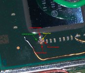
Let me know how your install goes. The switch lite has been giving me a hell of a time.
I have installed total 4 picofly's on v2, each of them boot into no sd on first try. I usually install picofly on v2 on avg 50min. But on this one I can tell for sure it is going to take a day or two.
Post automatically merged:

I'm going to follow a og method (Metal Shield cut). So, I can enjoy a blue light in the dark. Like a rgb vibes, just b 😂.
 

BlueBeans

Well-Known Member
Member
Joined
May 2, 2023
Messages
270
Trophies
0
Age
33
XP
280
Country
United States
I have installed total 4 picofly's on v2, each of them boot into no sd on first try. I usually install picofly on v2 on avg 50min. But on this one I can tell for sure it is going to take a day or two.
Post automatically merged:


I'm going to follow a og method (Metal Shield cut). So, I can enjoy a blue light in the dark. Like a rgb vibes, just b 😂.
Yeah, I've done about the same in terms of V2 and I did them with the mosfet. Booted the first time every time. I finally do a lite with the cable which I thought would be easy and its given me a run for my money
Post automatically merged:

I have installed total 4 picofly's on v2, each of them boot into no sd on first try. I usually install picofly on v2 on avg 50min. But on this one I can tell for sure it is going to take a day or two.
Post automatically merged:


I'm going to follow a og method (Metal Shield cut). So, I can enjoy a blue light in the dark. Like a rgb vibes, just b 😂.
I didn't even think about cutting the shield guess it's good i saw that before putting everything together. What do you do for the V2/V1? do you cut the shield there as well?
 

QuiTim

Well-Known Member
Member
Joined
Mar 30, 2023
Messages
758
Trophies
0
XP
1,191
Country
Albania
Hi,
I am getting screen flickering, slow performance and black lines when I boot to the CFW or OFW on a switch oled. Overall its glitchy and slow, but works fine in Hekate.

I installed the picofly and when I was installing it I noticed that, with the multimeter in Diode Mode, I was getting ~0.355v from the CPU. I am using a V2 ribbon cable from the Hwfly modchip. Could this be the issue?
Do you have pictures of installation?
 

bilalhassan341

Well-Known Member
Member
Joined
Apr 1, 2023
Messages
138
Trophies
0
XP
271
Country
United States
Yeah, I've done about the same in terms of V2 and I did them with the mosfet. Booted the first time every time. I finally do a lite with the cable which I thought would be easy and its given me a run for my money
Post automatically merged:


I didn't even think about cutting the shield guess it's good i saw that before putting everything together. What do you do for the V2/V1? do you cut the shield there as well?
I always cut the shield incase if there is error, or yellow light. With the shield cut I can see blue from the vent clearly. Btw it depend on you which method you want to follow. Before opening the switch shield I can tell that emmc is the best place by looking at the metal shield.
 
  • Like
Reactions: BlueBeans

QuiTim

Well-Known Member
Member
Joined
Mar 30, 2023
Messages
758
Trophies
0
XP
1,191
Country
Albania
Sorry for double posting.

I don't sadly and I am at work. I was just wondering what I should be checking.

This is my 7th installation and this never occurred. I can post pictures later in the day
I had a similar issue with an oled (but with hwfly).
After 2 days of banging my head on the wall I fixed it by changing 2 things:
- 1. I swaped the dat0 adapter for a old "corner" model (didn't have any other at hand at the time). It turns out the dat0 was giving good diode value but it was one of the shitty ones (could not confirm that it was shorting dat0 and dat1 but I had my doubts).
- 2. I ditched the flex cable (the one that connects clk, cmd, rst) because that flex cable was most likely causing interference on one of the lines so I wired everything manualy with 34awg and the issue fixed.

In your case, (although I didn't see the installation) I would first try to clean any residue flux on solder points, then change the wire, and reroute it as well (clean again).
If that does not work, i would reseat the dat0 (in case you did not set a permanent point by reballing)
 

abal1000x

Well-Known Member
Member
Joined
Jun 5, 2022
Messages
1,071
Trophies
0
XP
1,421
Country
Gaza Strip
Guys do you know the logical explanation why lite/v1/v2 lcd usually break after 4-5 years? While handphone lcd seems work for eternity.
 

provato

Active Member
Newcomer
Joined
May 1, 2014
Messages
41
Trophies
1
Age
39
XP
108
Country
Greece
hey all! I've got a problem with my second picofly installation on a mariko (v2).
I've done one very successfully.
one of the drain wires of the mosfet to the furthest capacitor beside the nividia chip detached and took the capacitor's pad with it! (yeah... ripped pad).
As you can see in the picture I attached, only the capacitor's ground pad remains, and I've carefully scraped all around the ripped pad to find a possible continuation of that ripped pad. Turns out there is ground all around this pad (checked with dmm)

I tried soldering the wire to the capacitor's ground pad but I get two long yellow flashes and one short yellow flash (==*) which means check mosfet I've read.

My question is, what can I do now? Is there any alternative solder point for one of the mosfets' drain?
 

Attachments

  • IMG_5441.JPG
    IMG_5441.JPG
    1.3 MB · Views: 28
  • Untitled-1.jpg
    Untitled-1.jpg
    1.3 MB · Views: 31

abal1000x

Well-Known Member
Member
Joined
Jun 5, 2022
Messages
1,071
Trophies
0
XP
1,421
Country
Gaza Strip
hey all! I've got a problem with my second picofly installation on a mariko (v2).
I've done one very successfully.
one of the drain wires of the mosfet to the furthest capacitor beside the nividia chip detached and took the capacitor's pad with it! (yeah... ripped pad).
As you can see in the picture I attached, only the capacitor's ground pad remains, and I've carefully scraped all around the ripped pad to find a possible continuation of that ripped pad. Turns out there is ground all around this pad (checked with dmm)

I tried soldering the wire to the capacitor's ground pad but I get two long yellow flashes and one short yellow flash (==*) which means check mosfet I've read.

My question is, what can I do now? Is there any alternative solder point for one of the mosfets' drain?
Basically you only need one. Those two cap are connected one to another.

There still capacitor on the right. The problem is you need a bigger cable, since there will be high current flows in there. I make a U-Turn to make it twice the current could flows.

https://gbatemp.net/threads/picofly-a-hwfly-switch-modchip.622701/post-10179786
 
  • Like
Reactions: provato

BlueBeans

Well-Known Member
Member
Joined
May 2, 2023
Messages
270
Trophies
0
Age
33
XP
280
Country
United States

QuiTim

Well-Known Member
Member
Joined
Mar 30, 2023
Messages
758
Trophies
0
XP
1,191
Country
Albania
I finally got this beauty today and it looks awesome.
Rev 1.1 has 47ohm resistors in place. Just one more week to go until I get the new Zelda Oled and a chance to try this out. Maybe I even build up the courage to do a perm. dat0 by then :D
 

Attachments

  • 20230609_174554.jpg
    20230609_174554.jpg
    964.7 KB · Views: 31
  • 20230609_174540.jpg
    20230609_174540.jpg
    1.2 MB · Views: 28
  • 20230609_174713.jpg
    20230609_174713.jpg
    675 KB · Views: 27
  • 20230609_175150.jpg
    20230609_175150.jpg
    2.8 MB · Views: 30
Last edited by QuiTim,

darviral

Member
Newcomer
Joined
Dec 12, 2020
Messages
21
Trophies
0
Age
37
XP
247
Country
Philippines
2 NS V2 Picofly w/ single mosfet & 2 Mosfet Done in 1hr 🎮💯
 

Attachments

  • VID_20230609_184630.mp4
    38.9 MB
  • IMG_20230609_222458.jpg
    IMG_20230609_222458.jpg
    4.1 MB · Views: 34
  • IMG_20230609_212434.jpg
    IMG_20230609_212434.jpg
    2.6 MB · Views: 31
  • IMG_20230609_212925.jpg
    IMG_20230609_212925.jpg
    4.2 MB · Views: 34
Last edited by darviral,
  • Like
Reactions: cgtchy0412

abal1000x

Well-Known Member
Member
Joined
Jun 5, 2022
Messages
1,071
Trophies
0
XP
1,421
Country
Gaza Strip
Do you think that a single mosfet if more effective than the cable or a double mosfet?
Its not about effective ness. Its about logical think.

Both cap actually connected. VDD connected to each other and GND connected to each other. Something like this (pardon me for the bad sketch)
photo_6061864563688716146_y.jpg


Basically the mosfet is used as a 'switch' to steal the power that goes to the soc. As long as the mosfet could hold the current flows there, then adding another mosfet to the same point is useless. Its just the same as adding another cable to split the current, so the maximum current flows is twice than before.

IRF8342 could hold 8.5A, i assume its continuous. So if its only short time, it could hold more. If ship happened, then the mosfet will burned. Since it is not, then the mosfet could hold the high current flows to DS.
 

BlueBeans

Well-Known Member
Member
Joined
May 2, 2023
Messages
270
Trophies
0
Age
33
XP
280
Country
United States
I finally got this beauty today and it looks awesome.
Rev 1.1 has 47ohm resistors in place. Just one more week to go until I get the new Zelda Oled and a chance to try this out. Maybe I even build up a courage to do a perm. dat0 until then :D
where did you get those?!?!
 

provato

Active Member
Newcomer
Joined
May 1, 2014
Messages
41
Trophies
1
Age
39
XP
108
Country
Greece
Basically you only need one. Those two cap are connected one to another.

There still capacitor on the right. The problem is you need a bigger cable, since there will be high current flows in there. I make a U-Turn to make it twice the current could flows.

https://gbatemp.net/threads/picofly-a-hwfly-switch-modchip.622701/post-10179786
now I get =** (=** eMMC init failure during glitch process) :( and it doesn't even go into OFW (black screen). Have I destroyed the switch?
 

BlueBeans

Well-Known Member
Member
Joined
May 2, 2023
Messages
270
Trophies
0
Age
33
XP
280
Country
United States
Its not about effective ness. Its about logical think.

Both cap actually connected. VDD connected to each other and GND connected to each other. Something like this (pardon me for the bad sketch)
View attachment 376943

Basically the mosfet is used as a 'switch' to steal the power that goes to the soc. As long as the mosfet could hold the current flows there, then adding another mosfet to the same point is useless. Its just the same as adding another cable to split the current, so the maximum current flows is twice than before.

IRF8342 could hold 8.5A, i assume its continuous. So if its only short time, it could hold more. If ship happened, then the mosfet will burned. Since it is not, then the mosfet could hold the high current flows to DS.
ok ill give it a try with a single mosfet. can you post a pic of your single mosfet install?
 

Site & Scene News

Popular threads in this forum

General chit-chat
Help Users
  • AcuteBulbasaurappears @ AcuteBulbasaurappears:
    @salazarcosplay Ah well I backed it up, but I didn't upgrade it. a long time ago
  • BigOnYa @ BigOnYa:
    @Xdqwerty I don't have a ROG ally
  • Xdqwerty @ Xdqwerty:
    @BigOnYa, i don't have one either
    +1
  • SylverReZ @ SylverReZ:
    @AcuteBulbasaurappears, A cute bulbasaur appears. :D
    +2
  • SylverReZ @ SylverReZ:
    @Psionic Roshambo, The Wii U gamepads are tied to the console's region, so its impossible to find a cheap gamepad that supports your model.
  • SylverReZ @ SylverReZ:
    Unless you modify your system, of course, and remove the region check.
  • Xdqwerty @ Xdqwerty:
    @SylverReZ, im now by episode 8 of lain
  • S @ salazarcosplay:
    @Xdqwerty can we discuss chrono trigger
  • S @ salazarcosplay:
    @Xdqwerty I like how the game had the middle ages 1000AD, the dark ages 600AD.It was great seeing the post robot apocalypse 2300 like Terminator and enter the matrix. some of mad max and fallout. 2300ad though it could had used more elements instead of just a generic ai uprising. It was a great idea for their judgement day to be 1999 Y2K.

    -great additions if they would have made an expansion or dlc in my opinion would be finding out humans trapped in a matrix -

    a follower having a cyborg character living tissue over metal endoskelleton like terminator, and the synths from fallout
  • S @ salazarcosplay:
    4After Zeal fell it would have been good to see more ancient eras. Perhaps Sumeria based in one area, then Egypt based in another area, Greek based in another area, then roman based in another area before the middle ages.---------

    ----between 1000ad and 1999 is a big gap they should have had the age of revolution like the american and French Revolution

    then the cowboyy era in one area of map and the Industrial revolution/age of enlightmentthen a ww1 and ww2 and a cold war era
  • S @ salazarcosplay:
    they could have added 75,000 bc like assassins creed. zeal was already establish in 12, 000 bc , soething before the kindom rose
  • S @ salazarcosplay:
    @Xdqwerty they could also add age of dscover, colonialism ect
    +1
  • S @ salazarcosplay:
    renaissance
  • S @ salazarcosplay:
    @Xdqwerty what did you think
  • S @ salazarcosplay:
    @Xdqwerty I think glenn (the frog) after becomming human had an affair with the queen
  • S @ salazarcosplay:
    so he is the great great great great grandfather of marle @Xdqwerty
  • S @ salazarcosplay:
    they made it like Lancelot from king arthur legends
  • BakerMan @ BakerMan:
    just found out i'm now taller than my dad
  • Xdqwerty @ Xdqwerty:
    @salazarcosplay, sorry i was busy
  • S @ salazarcosplay:
    @Xdqwerty thats completely fine
    +1
  • Xdqwerty @ Xdqwerty:
    @salazarcosplay,
    the ds version added a secret boss reference to chrono cross
  • S @ salazarcosplay:
    @Xdqwerty did you finish watching naruto shippuden and Boruto
    S @ salazarcosplay: @Xdqwerty did you finish watching naruto shippuden and Boruto