


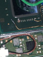
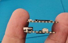
Let me know how your install goes. The switch lite has been giving me a hell of a time.Switch Lite points are tiny as hell compared to V2 or V1.
Edit: Just figured out that SDA and SCL are on the other side of this board.
You are using an out of date browser. It may not display this or other websites correctly.
You should upgrade or use an alternative browser.
You should upgrade or use an alternative browser.
Staff Posts
Recent threadmarks
sharing files
Important Posts
Recent threadmarks
Firmwares

Lite perfectly fit if you place the pico on top of the emmc.Let me know how your install goes. The switch lite has been giving me a hell of a time.
https://gbatemp.net/threads/picofly-a-hwfly-switch-modchip.622701/page-415#post-10167696
I have installed total 4 picofly's on v2, each of them boot into no sd on first try. I usually install picofly on v2 on avg 50min. But on this one I can tell for sure it is going to take a day or two.Let me know how your install goes. The switch lite has been giving me a hell of a time.
Post automatically merged:
I'm going to follow a og method (Metal Shield cut). So, I can enjoy a blue light in the dark. Like a rgb vibes, just bLite perfectly fit if you place the pico on top of the emmc.
https://gbatemp.net/threads/picofly-a-hwfly-switch-modchip.622701/page-415#post-10167696
 .
.Yeah, I've done about the same in terms of V2 and I did them with the mosfet. Booted the first time every time. I finally do a lite with the cable which I thought would be easy and its given me a run for my moneyI have installed total 4 picofly's on v2, each of them boot into no sd on first try. I usually install picofly on v2 on avg 50min. But on this one I can tell for sure it is going to take a day or two.
Post automatically merged:
I'm going to follow a og method (Metal Shield cut). So, I can enjoy a blue light in the dark. Like a rgb vibes, just b
Post automatically merged:
I didn't even think about cutting the shield guess it's good i saw that before putting everything together. What do you do for the V2/V1? do you cut the shield there as well?I have installed total 4 picofly's on v2, each of them boot into no sd on first try. I usually install picofly on v2 on avg 50min. But on this one I can tell for sure it is going to take a day or two.
Post automatically merged:
I'm going to follow a og method (Metal Shield cut). So, I can enjoy a blue light in the dark. Like a rgb vibes, just b

Do you have pictures of installation?Hi,
I am getting screen flickering, slow performance and black lines when I boot to the CFW or OFW on a switch oled. Overall its glitchy and slow, but works fine in Hekate.
I installed the picofly and when I was installing it I noticed that, with the multimeter in Diode Mode, I was getting ~0.355v from the CPU. I am using a V2 ribbon cable from the Hwfly modchip. Could this be the issue?
I always cut the shield incase if there is error, or yellow light. With the shield cut I can see blue from the vent clearly. Btw it depend on you which method you want to follow. Before opening the switch shield I can tell that emmc is the best place by looking at the metal shield.Yeah, I've done about the same in terms of V2 and I did them with the mosfet. Booted the first time every time. I finally do a lite with the cable which I thought would be easy and its given me a run for my money
Post automatically merged:
I didn't even think about cutting the shield guess it's good i saw that before putting everything together. What do you do for the V2/V1? do you cut the shield there as well?
Sorry for double posting.Do you have pictures of installation?
I don't sadly and I am at work. I was just wondering what I should be checking.
This is my 7th installation and this never occurred. I can post pictures later in the day
I had a similar issue with an oled (but with hwfly).Sorry for double posting.
I don't sadly and I am at work. I was just wondering what I should be checking.
This is my 7th installation and this never occurred. I can post pictures later in the day
After 2 days of banging my head on the wall I fixed it by changing 2 things:
- 1. I swaped the dat0 adapter for a old "corner" model (didn't have any other at hand at the time). It turns out the dat0 was giving good diode value but it was one of the shitty ones (could not confirm that it was shorting dat0 and dat1 but I had my doubts).
- 2. I ditched the flex cable (the one that connects clk, cmd, rst) because that flex cable was most likely causing interference on one of the lines so I wired everything manualy with 34awg and the issue fixed.
In your case, (although I didn't see the installation) I would first try to clean any residue flux on solder points, then change the wire, and reroute it as well (clean again).
If that does not work, i would reseat the dat0 (in case you did not set a permanent point by reballing)

hey all! I've got a problem with my second picofly installation on a mariko (v2).
I've done one very successfully.
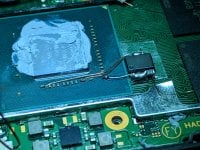
one of the drain wires of the mosfet to the furthest capacitor beside the nividia chip detached and took the capacitor's pad with it! (yeah... ripped pad).
As you can see in the picture I attached, only the capacitor's ground pad remains, and I've carefully scraped all around the ripped pad to find a possible continuation of that ripped pad. Turns out there is ground all around this pad (checked with dmm)
I tried soldering the wire to the capacitor's ground pad but I get two long yellow flashes and one short yellow flash (==*) which means check mosfet I've read.
My question is, what can I do now? Is there any alternative solder point for one of the mosfets' drain?
I've done one very successfully.
one of the drain wires of the mosfet to the furthest capacitor beside the nividia chip detached and took the capacitor's pad with it! (yeah... ripped pad).
As you can see in the picture I attached, only the capacitor's ground pad remains, and I've carefully scraped all around the ripped pad to find a possible continuation of that ripped pad. Turns out there is ground all around this pad (checked with dmm)
I tried soldering the wire to the capacitor's ground pad but I get two long yellow flashes and one short yellow flash (==*) which means check mosfet I've read.
My question is, what can I do now? Is there any alternative solder point for one of the mosfets' drain?
Attachments
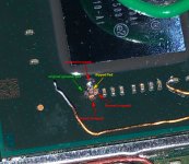
Basically you only need one. Those two cap are connected one to another.hey all! I've got a problem with my second picofly installation on a mariko (v2).
I've done one very successfully.
one of the drain wires of the mosfet to the furthest capacitor beside the nividia chip detached and took the capacitor's pad with it! (yeah... ripped pad).
As you can see in the picture I attached, only the capacitor's ground pad remains, and I've carefully scraped all around the ripped pad to find a possible continuation of that ripped pad. Turns out there is ground all around this pad (checked with dmm)
I tried soldering the wire to the capacitor's ground pad but I get two long yellow flashes and one short yellow flash (==*) which means check mosfet I've read.
My question is, what can I do now? Is there any alternative solder point for one of the mosfets' drain?
There still capacitor on the right. The problem is you need a bigger cable, since there will be high current flows in there. I make a U-Turn to make it twice the current could flows.
https://gbatemp.net/threads/picofly-a-hwfly-switch-modchip.622701/post-10179786
Do you think that a single mosfet if more effective than the cable or a double mosfet?Basically you only need one. Those two cap are connected one to another.
There still capacitor on the right. The problem is you need a bigger cable, since there will be high current flows in there. I make a U-Turn to make it twice the current could flows.
https://gbatemp.net/threads/picofly-a-hwfly-switch-modchip.622701/post-10179786

Add SCL/SDA wires to lower the glitch requierements so single cap connection could workMy question is, what can I do now?
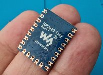
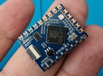
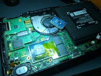
I finally got this beauty today and it looks awesome.
Rev 1.1 has 47ohm resistors in place. Just one more week to go until I get the new Zelda Oled and a chance to try this out. Maybe I even build up the courage to do a perm. dat0 by then
Rev 1.1 has 47ohm resistors in place. Just one more week to go until I get the new Zelda Oled and a chance to try this out. Maybe I even build up the courage to do a perm. dat0 by then
Attachments

Last edited by QuiTim,

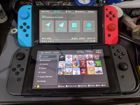
2 NS V2 Picofly w/ single mosfet & 2 Mosfet Done in 1hr 

Attachments
Last edited by darviral,
Its not about effective ness. Its about logical think.Do you think that a single mosfet if more effective than the cable or a double mosfet?
Both cap actually connected. VDD connected to each other and GND connected to each other. Something like this (pardon me for the bad sketch)
Basically the mosfet is used as a 'switch' to steal the power that goes to the soc. As long as the mosfet could hold the current flows there, then adding another mosfet to the same point is useless. Its just the same as adding another cable to split the current, so the maximum current flows is twice than before.
IRF8342 could hold 8.5A, i assume its continuous. So if its only short time, it could hold more. If ship happened, then the mosfet will burned. Since it is not, then the mosfet could hold the high current flows to DS.
where did you get those?!?!I finally got this beauty today and it looks awesome.
Rev 1.1 has 47ohm resistors in place. Just one more week to go until I get the new Zelda Oled and a chance to try this out. Maybe I even build up a courage to do a perm. dat0 until then
now I get =** (=** eMMC init failure during glitch process)Basically you only need one. Those two cap are connected one to another.
There still capacitor on the right. The problem is you need a bigger cable, since there will be high current flows in there. I make a U-Turn to make it twice the current could flows.
https://gbatemp.net/threads/picofly-a-hwfly-switch-modchip.622701/post-10179786
and it doesn't even go into OFW (black screen). Have I destroyed the switch?In aliexpress they already sold it again. I have checked it and its correct 47 ohms. So they revised it all last weekwhere did you get those?!?!
ok ill give it a try with a single mosfet. can you post a pic of your single mosfet install?Its not about effective ness. Its about logical think.
Both cap actually connected. VDD connected to each other and GND connected to each other. Something like this (pardon me for the bad sketch)
View attachment 376943
Basically the mosfet is used as a 'switch' to steal the power that goes to the soc. As long as the mosfet could hold the current flows there, then adding another mosfet to the same point is useless. Its just the same as adding another cable to split the current, so the maximum current flows is twice than before.
IRF8342 could hold 8.5A, i assume its continuous. So if its only short time, it could hold more. If ship happened, then the mosfet will burned. Since it is not, then the mosfet could hold the high current flows to DS.
Similar threads
- Replies
- 5
- Views
- 3K
- Replies
- 2
- Views
- 930
- Replies
- 42
- Views
- 7K
Site & Scene News
New Hot Discussed
-
-
22K views
Modders hint at potential kernel exploit hack for Xbox One consoles
It's been a while since Microsoft released the Xbox One, and despite its age, there haven't been any reliable softmod methods to hack the console. Until now. A post... -
22K views
Majora’s Mask PC port 2Ship2Harkinian gets its first release
After several months of work, the Harbour Masters 64 team have released their first public build of 2Ship2Harkinian, a feature-rich Majora's Mask PC port. This comes... -
19K views
Mario Builder 64 is the N64's answer to Super Mario Maker
With the vast success of Super Mario Maker and its Switch sequel Super Mario Maker 2, Nintendo fans have long been calling for "Maker" titles for other iconic genres... -
18K views
The founder of Oculus is releasing a $199 FPGA Game Boy system
Palmer Luckey is known for his pursuits into the world of virtual reality, having founded Oculus and designed the Rift VR headset. Prior to the $2 billion dollar... -
15K views
Nintendo takes down the Breath of the Wild randomizer mod from Gamebanana
Another day, another Nintendo DMCA takedown against fan-made content. Just a few minutes ago, Nintendo issued a DMCA takedown notice against a widely known and...by ShadowOne333 106 -
15K views
The Kingdom Hearts games are coming to Steam
After a little more than three years of exclusivity with the Epic Games Store, Square Enix has decided to bring their beloved Kingdom Hearts franchise to Steam. The... -
14K views
Doom for SNES full source code released by former Sculptured Software employees
The complete source code for the Super Nintendo Entertainment System (SNES) version of Doom has been released on archive.org. Although some of the code was partially... -
12K views
Select PlayStation 2 games are coming to PlayStation 5
Sony is once more attempting to reintroduce players to their older library of games by re-releasing classic PlayStation 2 titles onto the PlayStation Store. During... -
12K views
Skyward Sword HD randomizer announced with release date and trailer
Skyward Sword is a divisive title in the Zelda series. Hailed with praise at launch with a 93 Metacritic average, the game since received criticism for the... -
10K views
PlayStation State of Play May 2024 showcase - God of War: Ragnarok coming to PC
The latest State of Play is here. This is PlayStation's Summer showcase, providing updates to new updates on upcoming games and brand new reveals. The 35-minute...
-
-
-
169 replies
The founder of Oculus is releasing a $199 FPGA Game Boy system
Palmer Luckey is known for his pursuits into the world of virtual reality, having founded Oculus and designed the Rift VR headset. Prior to the $2 billion dollar...by Chary -
131 replies
Modders hint at potential kernel exploit hack for Xbox One consoles
It's been a while since Microsoft released the Xbox One, and despite its age, there haven't been any reliable softmod methods to hack the console. Until now. A post...by Chary -
108 replies
Majora’s Mask PC port 2Ship2Harkinian gets its first release
After several months of work, the Harbour Masters 64 team have released their first public build of 2Ship2Harkinian, a feature-rich Majora's Mask PC port. This comes...by Scarlet -
106 replies
Nintendo takes down the Breath of the Wild randomizer mod from Gamebanana
Another day, another Nintendo DMCA takedown against fan-made content. Just a few minutes ago, Nintendo issued a DMCA takedown notice against a widely known and...by ShadowOne333 -
91 replies
The Kingdom Hearts games are coming to Steam
After a little more than three years of exclusivity with the Epic Games Store, Square Enix has decided to bring their beloved Kingdom Hearts franchise to Steam. The...by Chary -
79 replies
Select PlayStation 2 games are coming to PlayStation 5
Sony is once more attempting to reintroduce players to their older library of games by re-releasing classic PlayStation 2 titles onto the PlayStation Store. During...by Chary -
71 replies
Nintendo Direct announced for tomorrow, June 18th, 2024
Nintendo have officially announced a Nintendo Direct for tomorrow, June 18th. The show will focus on Switch titles releasing this year and they have explicitly...by shaunj66 -
66 replies
Mario Builder 64 is the N64's answer to Super Mario Maker
With the vast success of Super Mario Maker and its Switch sequel Super Mario Maker 2, Nintendo fans have long been calling for "Maker" titles for other iconic genres...by Scarlet -
64 replies
PlayStation State of Play May 2024 showcase - God of War: Ragnarok coming to PC
The latest State of Play is here. This is PlayStation's Summer showcase, providing updates to new updates on upcoming games and brand new reveals. The 35-minute...by Chary -
64 replies
Doom for SNES full source code released by former Sculptured Software employees
The complete source code for the Super Nintendo Entertainment System (SNES) version of Doom has been released on archive.org. Although some of the code was partially...by shaunj66
-
Popular threads in this forum
General chit-chat
-
 K3Nv2
Loading…
K3Nv2
Loading… -
HiradeGirl
Loading… -
 Sicklyboy
Loading…
Sicklyboy
Loading…
-
-
-
-
-
-
 @
BakerMan:
if you have a habitable basement, the heat shouldn't be down there and that's where you should hang out
@
BakerMan:
if you have a habitable basement, the heat shouldn't be down there and that's where you should hang out -
-
-
-
-
-
-
-
-
-
@
BakerMan:
fuck this heatwave, i don't usually sleep with a fan, but i believe the fan is getting put on the bed rather than beside it
-
-
-
 @
BigOnYa:
Yea it was 96 F for the high, 78 F for the low today, in Ohio, bout same for bakerman in Michigan
@
BigOnYa:
Yea it was 96 F for the high, 78 F for the low today, in Ohio, bout same for bakerman in Michigan -
-
-
-
-
-