


Where can i got 2.75 firmware? In github i can see only 2.74 rolled back for 2.73.Firmware 2.75 maybe fix this issue too:
You are using an out of date browser. It may not display this or other websites correctly.
You should upgrade or use an alternative browser.
You should upgrade or use an alternative browser.
Staff Posts
Recent threadmarks
sharing files
Important Posts
Recent threadmarks
Firmwares
hi. here https://github.com/rehius/usk/releasesWhere can i got 2.75 firmware? In github i can see only 2.74 rolled back for 2.73.


https://github.com/rehius/usk/releasesWhere can i got 2.75 firmware? In github i can see only 2.74 rolled back for 2.73.

top off the thread important postWhere can i got 2.75 firmware? In github i can see only 2.74 rolled back for 2.73.

Question on reballing the eMMC, what temps and air settings are you guys using? I've been using 380 @ 50% and go nice and slow. I've heard the eMMC can be damaged by heat so didn't want to go too hot.
160 for a minute, 265 for a minute, 370 until the emmc comes loose which usually happens after around 40 seconds. 20% airspeed always (but this varies depending on the station.)

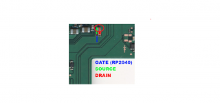
he was refering to all switches in Generel, if u dont know what D and S point is check the PicofFly Guide
I managed to attach CMD point. I tugged a little, but the connection seems a tiny bit loose. I don't want to pull too hard, but it does appear to be attached with the moderate force I have put on it. Should I just leave it be?
From what I can see.
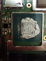
I am getting BSOD after trying picofly. I just applied solder to tge solder points and thought I will complete it in daylight.
Went through the forum, cleaned my soldered points and flux but still BSOD.
Attaching images, please someone have a look at it.

About your issue.
Since you could goes to hekate, then i think the dram connection should be okay.
I remember someone whose dram trace got disconnected, cannot even goes to hekate.
Have you tried to reball the emmc, or use the permanent method?
If you are not confident, dont do it.
Reball, indeed need basic skill and appropriate tool to safely executed.
No reball, as I don't have a decent BGA system.
I took the DAT0 adapter and have already exchanged it for another one. Unfortunately, the problem is still the same. The question is, why did the switch crash shortly before the end when creating the Nand ? Maybe a short circuit between DAT0 & DAT1 and now the nand is corrupted ?
Hey guys! Got an OLED with SKHynix, did eMMC reball and with RP2040-zero (3x47Ohm) + FW2.73 I sometimes get slow glitch time (up to 15s and other times 2-3s). Tried adding extra 47 Ohm on CLK and CMD, but the timming did not improve. Once booted, the console works well and the eMMC has the correct speed.
Is this SKHynix "stubborn" or is there some room to improve? What was "weird" as well is that usually I read between 0.450V-0.5V on eMMC (red on GND), but on this console they're around 0.55V.
Is this SKHynix "stubborn" or is there some room to improve? What was "weird" as well is that usually I read between 0.450V-0.5V on eMMC (red on GND), but on this console they're around 0.55V.

Its not only skhynix, almost all mariko have that weird issue.Hey guys! Got an OLED with SKHynix, did eMMC reball and with RP2040-zero (3x47Ohm) + FW2.73 I sometimes get slow glitch time (up to 15s and other times 2-3s). Tried adding extra 47 Ohm on CLK and CMD, but the timming did not improve. Once booted, the console works well and the eMMC has the correct speed.
Is this SKHynix "stubborn" or is there some room to improve? What was "weird" as well is that usually I read between 0.450V-0.5V on eMMC (red on GND), but on this console they're around 0.55V.
Average on 3s but sometimes its just out of sync and re-search the glitch point again which resulted the long glitch time.
The only differences between erista and mariko (beside the cpu ofcourse) on the 1V line is that in marista there is EM filter put on, while on mariko doesn't have it. Maybe this could result that weird random time issue, but i am not convinced enough on that reasoning.

I told a flex is better since it doesn't have that short coming of having a rigid structure, though the only problem here is the price since you have to order bulk to make it worthawhile otherwise they will charge you an arm.I always choose the lesser risk.
My step is first paste and reball the bottom adapter. If the bending is negligible than goes to reflow it to the mainboard pcb. Then check the continuity of cmd and vdd. Then paste and reball the emmc, then reflow to the adapter. Then check again the continuity of cmd and vdd to the main board.
I choose this order because this is the lesser risk.
If i Reflow the emmc to the adapter first. If its failed then i need to repeat the reballing emmc and reflow it to the adapter again. This might broke the emmc if i do it again and again.
I prefer reball the adapter first. If its failed, the adapter itself is cheap only $1, not much loose. And the mainboard pcb are rigid, its >5layer. So its not easily broken compare to the emmc.
I always choose lesser risk and lowest price as much as possible. Complexity is not a concern for me. As long as the risk is less.
Subjectively i prefer green adapter than the flex.I told a flex is better since it doesn't have that short coming of having a rigid structure, though the only problem here is the price since you have to order bulk to make it worthawhile otherwise they will charge you an arm.
If you want to reduce the flex price, try to create it yourself on kicad and manufacture it on the jlcpcb.
Subjectively i prefer green adapter than the flex.
If you want to reduce the flex price, try to create it yourself on kicad and manufacture it on the jlcpcb.
Jlcpcb butchered the deign I sent them. I went with another fab but the price was steep.
- Joined
- Sep 2, 2020
- Messages
- 1,320
- Trophies
- 0
- Age
- 39
- Location
- TORONTO
- Website
- form.jotform.com
- XP
- 2,259
- Country

Missing resistor. I believe it's 100 ohmI am getting BSOD after trying picofly. I just applied solder to tge solder points and thought I will complete it in daylight.
Went through the forum, cleaned my soldered points and flux but still BSOD.
Attaching images, please someone have a look at it.
Attachments
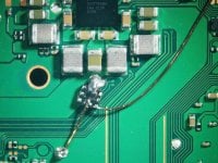
I changed from flex cable to backside mosfet installation which works fine. Just in case I will ruin the cap near the mosfet on an OLED. Can anyone help me what cap it is that I can order some spare sparts ?
or you can do this install instead
Attachments
or you can do this install instead
uh - was not aware of that. Does it work in the same way / speed etc. or any disadvantages ? Indeed this looks safer for me...
works exactly the same, but far easier to installuh - was not aware of that. Does it work in the same way / speed etc. or any disadvantages ? Indeed this looks safer for me...
works exactly the same, but far easier to install
Great! Thanks for that info. This is only working for OLED or are there also safer methods for V2 / lites etc. for the mosfet installations ?
there are, but you normally wouldn't remove the motherboard on those so it adds complexity in other ways instead. Here are two alternatives for the switch liteGreat! Thanks for that info. This is only working for OLED or are there also safer methods for V2 / lites etc. for the mosfet installations ?
Great! Thanks for that info. This is only working for OLED or are there also safer methods for V2 / lites etc. for the mosfet installations ?
See this post https://gbatemp.net/threads/picofly-a-hwfly-switch-modchip.622701/page-579#post-10200708
there should be similar positions for v1/v2, I didn't check. Having to remove the motherboard makes it not worth it for me
Similar threads
- Replies
- 5
- Views
- 2K
- Replies
- 2
- Views
- 731
- Replies
- 42
- Views
- 7K
Site & Scene News
New Hot Discussed
-
-
34K views
New static recompiler tool N64Recomp aims to seamlessly modernize N64 games
As each year passes, retro games become harder and harder to play, as the physical media begins to fall apart and becomes more difficult and expensive to obtain. The... -
29K views
Nintendo officially confirms Switch successor console, announces Nintendo Direct for next month
While rumors had been floating about rampantly as to the future plans of Nintendo, the President of the company, Shuntaro Furukawa, made a brief statement confirming... -
26K views
Name the Switch successor: what should Nintendo call its new console?
Nintendo has officially announced that a successor to the beloved Switch console is on the horizon. As we eagerly anticipate what innovations this new device will... -
15K views
DOOM has been ported to the retro game console in Persona 5 Royal
DOOM is well-known for being ported to basically every device with some kind of input, and that list now includes the old retro game console in Persona 5 Royal... -
14K views
Mario Builder 64 is the N64's answer to Super Mario Maker
With the vast success of Super Mario Maker and its Switch sequel Super Mario Maker 2, Nintendo fans have long been calling for "Maker" titles for other iconic genres... -
14K views
Anbernic reveals the RG35XXSP, a GBA SP-inspired retro handheld
Retro handheld manufacturer Anbernic has revealed its first clamshell device: the Anbernic RG35XXSP. As the suffix indicates, this handheld's design is inspired by... -
13K views
Majora’s Mask PC port 2Ship2Harkinian gets its first release
After several months of work, the Harbour Masters 64 team have released their first public build of 2Ship2Harkinian, a feature-rich Majora's Mask PC port. This comes... -
12K views
"Nintendo World Championships: NES Edition", a new NES Remix-like game, launching July 18th
After rumour got out about an upcoming NES Edition release for the famed Nintendo World Championships, Nintendo has officially unveiled the new game, titled "Nintendo...by ShadowOne333 78 -
12K views
Microsoft is closing down several gaming studios, including Tango Gameworks and Arkane Austin
The number of layoffs and cuts in the videogame industry sadly continue to grow, with the latest huge layoffs coming from Microsoft, due to what MIcrosoft calls a...by ShadowOne333 65 -
11K views
Ubisoft reveals 'Assassin's Creed Shadows' which is set to launch later this year
Ubisoft has today officially revealed the next installment in the Assassin's Creed franchise: Assassin's Creed Shadows. This entry is set in late Sengoku-era Japan...
-
-
-
322 replies
Name the Switch successor: what should Nintendo call its new console?
Nintendo has officially announced that a successor to the beloved Switch console is on the horizon. As we eagerly anticipate what innovations this new device will...by Costello -
235 replies
Nintendo officially confirms Switch successor console, announces Nintendo Direct for next month
While rumors had been floating about rampantly as to the future plans of Nintendo, the President of the company, Shuntaro Furukawa, made a brief statement confirming...by Chary -
141 replies
New static recompiler tool N64Recomp aims to seamlessly modernize N64 games
As each year passes, retro games become harder and harder to play, as the physical media begins to fall apart and becomes more difficult and expensive to obtain. The...by Chary -
99 replies
Majora’s Mask PC port 2Ship2Harkinian gets its first release
After several months of work, the Harbour Masters 64 team have released their first public build of 2Ship2Harkinian, a feature-rich Majora's Mask PC port. This comes...by Scarlet -
96 replies
Ubisoft reveals 'Assassin's Creed Shadows' which is set to launch later this year
Ubisoft has today officially revealed the next installment in the Assassin's Creed franchise: Assassin's Creed Shadows. This entry is set in late Sengoku-era Japan...by Prans -
88 replies
The Kingdom Hearts games are coming to Steam
After a little more than three years of exclusivity with the Epic Games Store, Square Enix has decided to bring their beloved Kingdom Hearts franchise to Steam. The...by Chary -
78 replies
"Nintendo World Championships: NES Edition", a new NES Remix-like game, launching July 18th
After rumour got out about an upcoming NES Edition release for the famed Nintendo World Championships, Nintendo has officially unveiled the new game, titled "Nintendo...by ShadowOne333 -
71 replies
DOOM has been ported to the retro game console in Persona 5 Royal
DOOM is well-known for being ported to basically every device with some kind of input, and that list now includes the old retro game console in Persona 5 Royal...by relauby -
65 replies
Microsoft is closing down several gaming studios, including Tango Gameworks and Arkane Austin
The number of layoffs and cuts in the videogame industry sadly continue to grow, with the latest huge layoffs coming from Microsoft, due to what MIcrosoft calls a...by ShadowOne333 -
64 replies
Select PlayStation 2 games are coming to PlayStation 5
Sony is once more attempting to reintroduce players to their older library of games by re-releasing classic PlayStation 2 titles onto the PlayStation Store. During...by Chary
-