Switch OLED issues with modchip, blue screen without

RubyRoid

Well-Known Member
OP
Newcomer
Joined
Jan 27, 2014
Messages
76
Trophies
0
XP
427
Country
Cyprus
I'm having issues with my freshly modded Switch OLED.

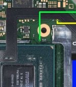
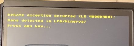
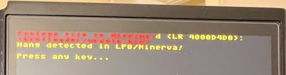
It was working and booting fine as soon as I installed the modchip but it was late so I shut it down and put it on charger for the night. The next day I went to install a larger SD card and got an error message. I've tried the old card but that didn't help. I've tried several other known good cards with no success. I've opened an issue in the hekate github repo and got a response that it's either fake or corrupted SD card or the SD connector itself (Update: contacted CTCaer directly and we came to conclusion that the issue is with one of the RAM modules). I don't think it's either one of those since I've been using tested good cards and opened the Switch and carefully inspected the SD connector and found no issues, all the pins look fine, nothing is bent or damaged.

Since I couldn't make the modchip work I decided to disconnect it. I desoldered and isolated all the wires from the chip and tried to boot the console. Got a blue screen. Tried to boot it holding the VOL+ and VOL- buttons but still getting the blue screen.

I'm not sure if simply desoldering the wires from the chip is enough to properly unmod the Switch but I couldn't find any proper instructions online.

Is there a way to make my Switch work again?
 

Attachments

  • fN1NdQc.jpeg
    fN1NdQc.jpeg
    170.2 KB · Views: 173
  • ZqObmfH.jpeg
    ZqObmfH.jpeg
    137 KB · Views: 153
Last edited by RubyRoid,

RubyRoid

Well-Known Member
OP
Newcomer
Joined
Jan 27, 2014
Messages
76
Trophies
0
XP
427
Country
Cyprus
did you uninstall the chip and when you turn on it display blue screen?
Yeah, I desoldered and isolated all the wires from the modchip and also disconnected the flex cable that's coming to the modchip from the CPU. Getting the blue screen when turning on the Switch. It doesn't show any logos or anything, just the blue screen.
 

urherenow

Well-Known Member
Member
Joined
Mar 8, 2009
Messages
4,810
Trophies
2
Age
48
Location
Japan
XP
3,717
Country
United States
You likely either used too little or way too much thermal paste, and an unlucky set of circumstances following, cracked a connection on a cpu solder ball. Fix for that... reflow. Have a heat gun?

This is assuming you immediately get the blue screen. Like... you can't even bring up maintenance mode...

 
Last edited by urherenow,

RubyRoid

Well-Known Member
OP
Newcomer
Joined
Jan 27, 2014
Messages
76
Trophies
0
XP
427
Country
Cyprus
You likely either used too little or way too much thermal paste, and an unlucky set of circumstances following, cracked a connection on a cpu solder ball. Fix for that... reflow. Have a heat gun?

This is assuming you immediately get the blue screen. Like... you can't even bring up maintenance mode...


The thermal paste was fresh so I simply reused it. Sure I needed to clean some leftovers on the chip but that amount is negligible. I also tried to apply pressure on the chip as shown in the video at 7:41 but that didn't help. Not sure it's the problem with the chip pads.
 

urherenow

Well-Known Member
Member
Joined
Mar 8, 2009
Messages
4,810
Trophies
2
Age
48
Location
Japan
XP
3,717
Country
United States
if it's not a reflow issue, then it must be your mod. Do you have a microscope that takes pictures? Post your clk, cmd, and flex cable (caps) solder points. Also, test cmd to the cpu frame with a meter. It's not just hard to get that point down, it's super easy to expose a bit of ground plane and short it... even while assembling (putting the screw in where the wire should be trained around the screw hole. I myself, don't use that route. I put the wire through the shield clip hole, and the solder mask to hold the wire steady is actually under the cpu shield).
 
Last edited by urherenow,

RubyRoid

Well-Known Member
OP
Newcomer
Joined
Jan 27, 2014
Messages
76
Trophies
0
XP
427
Country
Cyprus
if it's not a reflow issue, then it must be your mod. Do you have a microscope that takes pictures? Post your clk, cmd, and flex cable (caps) solder points. Also, test cmd to the cpu frame with a meter. It's not just hard to get that point down, it's super easy to expose a bit of ground plane and short it... even while assembling (putting the screw in where the wire should be trained around the screw hole. I myself, don't use that route. I put the wire through the shield clip hole, and the solder mask to hold the wire steady is actually under the cpu shield).
I don't have a microscope but do have a mirrorless camera with good zoom. I've actually recorder the whole installation process, so I can take the screenshots from the footage. Since then I've covered the CLK and CMD point with solder mask. I don't know how to remove it safely to take more shots.
 

Rodel

Well-Known Member
Member
Joined
Sep 10, 2020
Messages
116
Trophies
0
XP
573
Country
Philippines
if no chip installed and it is a bluescreen means the APU is the problem..need to reflow or check the A CMD because that resistor is killed if you solder long..it should 10k ohm read if you use multimeter
 

urherenow

Well-Known Member
Member
Joined
Mar 8, 2009
Messages
4,810
Trophies
2
Age
48
Location
Japan
XP
3,717
Country
United States
You don't need to remove the mask. You took the wires off of the mod chip, so use the open end of the wires to check your readings in diode mode...

Looks to me like your wires are too big. What are you using? And you tried this without a microscope? That was not smart... I had a cheap sub-$50 scope on my first attempt, and I screwed it up. The one I have now was only like $79, and has a 7" screen, and can snap/video... After seeing the difference, I felt stupid for ever trying with the smaller scope (it didn't leave much room to work the iron, either)

It's hard to tell with these pics. I can't see clk joint at all. The wire looks way too big for such a small point, and I can't even tell if there's enough solder there. You really shouldn't use bigger than 0.1mm on clk and cmd. For future reference, you never want to mask right on top of a point like that. get it close to prevent wiggling, but don't cover it, because now I would never try to fix that with a proper wire myself. Trying to remove the mask would likely pull the pad.
 

RubyRoid

Well-Known Member
OP
Newcomer
Joined
Jan 27, 2014
Messages
76
Trophies
0
XP
427
Country
Cyprus
if no chip installed and it is a bluescreen means the APU is the problem..need to reflow or check the A CMD because that resistor is killed if you solder long..it should 10k ohm read if you use multimeter
I did manage to safely remove solder mask from CMD point, the resistor measures around 4.66 - 4.7 kOhm. Could that be an issue?
 

RubyRoid

Well-Known Member
OP
Newcomer
Joined
Jan 27, 2014
Messages
76
Trophies
0
XP
427
Country
Cyprus
You don't need to remove the mask. You took the wires off of the mod chip, so use the open end of the wires to check your readings in diode mode...

Looks to me like your wires are too big. What are you using? And you tried this without a microscope? That was not smart... I had a cheap sub-$50 scope on my first attempt, and I screwed it up. The one I have now was only like $79, and has a 7" screen, and can snap/video... After seeing the difference, I felt stupid for ever trying with the smaller scope (it didn't leave much room to work the iron, either)

It's hard to tell with these pics. I can't see clk joint at all. The wire looks way too big for such a small point, and I can't even tell if there's enough solder there. You really shouldn't use bigger than 0.1mm on clk and cmd. For future reference, you never want to mask right on top of a point like that. get it close to prevent wiggling, but don't cover it, because now I would never try to fix that with a proper wire myself. Trying to remove the mask would likely pull the pad.
I get a reading around 0.501 in the diode mode between GND and the CLK point. I used 0.2mm wire. I agree that it would be better to have a microscope but it's not that bad using the camera connected to PC through HDMI and looking at the monitor. Which microscope would you recommend?
Should I go ahead and replace the CLK and CMD wires with 0.1mm?
 

Rodel

Well-Known Member
Member
Joined
Sep 10, 2020
Messages
116
Trophies
0
XP
573
Country
Philippines
there is an alternative need to hard reset
I get a reading around 0.501 in the diode mode between GND and the CLK point. I used 0.2mm wire. I agree that it would be better to have a microscope but it's not that bad using the camera connected to PC through HDMI and looking at the monitor. Which microscope would you recommend?
Should I go ahead and replace the CLK and CMD wires with 0.1mm?
its ok if you use 0.2mm. i use AWG36 teflon wire..did you try to hard reset your switch?
 

urherenow

Well-Known Member
Member
Joined
Mar 8, 2009
Messages
4,810
Trophies
2
Age
48
Location
Japan
XP
3,717
Country
United States
This is the one I bought. Along with a bunch of the tools recommended by sthetix

https://www.aliexpress.com/wholesale?catId=0&initiative_id=SB_20220824032426&SearchText=KKMOON+G1200

You can also connect it to a PC with a regular microsd cable to view live on a big monitor. Snaps and Video can also be done without PC. Although... the micro sd card slot is kind of dodgy... I'm affraid I'll break it if I try to take the card out again. But good thing You have a menu of choices when plugging it in to PC with USB (Camera, mass storage, and something else I forget right now... maybe firmware update or something...). Considering the price, I'm really happy with the purchase.

The movable/detachable lights are not powered by the scope though... they have their own USB cable for power.

Being sure your solder joints are ok, I'd leave them alone. It's just that they are so much stronger than the points you're soldering too, many people knock that cmd resistor right off the board while trying to get the wire soldered.
 
Last edited by urherenow,

RubyRoid

Well-Known Member
OP
Newcomer
Joined
Jan 27, 2014
Messages
76
Trophies
0
XP
427
Country
Cyprus
This is the one I bought. Along with a bunch of the tools recommended by sthetix

https://www.aliexpress.com/wholesale?catId=0&initiative_id=SB_20220824032426&SearchText=KKMOON+G1200

You can also connect it to a PC with a regular microsd cable to view live on a big monitor. Snaps and Video can also be done without PC. Although... the micro sd card slot is kind of dodgy... I'm affraid I'll break it if I try to take the card out again. But good thing You have a menu of choices when plugging it in to PC with USB (Camera, mass storage, and something else I forget right now... maybe firmware update or something...). Considering the price, I'm really happy with the purchase.

The movable/detachable lights are not powered by the scope though... they have their own USB cable for power.

Being sure your solder joints are ok, I'd leave them alone. It's just that they are so much stronger than the points you're soldering too, many people knock that cmd resistor right off the board while trying to get the wire soldered.
Thanks, I was thinking about getting a digital microscope for a long time, will take a look at that model of yours!

Regarding the joints, I'm pretty sure they are fine judging by the readings in the diode mode. After the issue arised, I also tried to reset the modchip and performed the trainig again, it worked fine. But that still doesn't explain why my Switch doesn't boot either with or without modchip. Sadly I'm at a loss right now.
 

urherenow

Well-Known Member
Member
Joined
Mar 8, 2009
Messages
4,810
Trophies
2
Age
48
Location
Japan
XP
3,717
Country
United States
You mean holding VOL+ and VOL- together and then Power? Yes, it shows blue screen any way.
Leave the blue screen on until your battery dies. Then plug it in and let it completely recharge. I doubt that helps with this issue, but I've seen enough people comment that it helped them to give it a shot, if I don't know what else to do. I still think you should try to reflow it if you have the tools. I don't recall anyone getting a bsod from dat0, so it's gotta be the cpu.

Unless... you got a corrupt boot0/boot1. Which chip, and which firmware?

your flex cable looks like the OLED chip I have, Flash hwfly-nx firmware 0.7.1 to it, and re-train. Maybe it'll fix the payload in boot0? And whatever you do... do NOT put the usb adapter in upside-down. That'll insta-brick the USB function of the chip. Stupid design...
 

Site & Scene News

Popular threads in this forum

General chit-chat
Help Users
  • No one is chatting at the moment.
    Veho @ Veho: Wow, only $700?