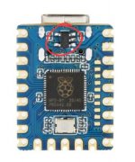
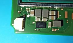
Might be a faulty rp2040. Did you remove the LDO from the back?SOOO. i have a V1 acting up. Sometimes the chip does not turn on (no light on the LED),and it opens OFW.
I have replaced gnd and 3.3v wires to 30 awg,same result.
I have "reflowed" the solder on the connections and still same result.
Here are some pictures
View attachment 407280
View attachment 407281
View attachment 407282
View attachment 407283
You are using an out of date browser. It may not display this or other websites correctly.
You should upgrade or use an alternative browser.
You should upgrade or use an alternative browser.
Picofly AIO Thread
- Thread starter Adran_Marit
- Start date
- Views 526,092
- Replies 3,360
- Likes 60

Have you tried 47ohm resistors on DAT0/CMD?SOOO. i have a V1 acting up. Sometimes the chip does not turn on (no light on the LED),and it opens OFW.
I have replaced gnd and 3.3v wires to 30 awg,same result.
I have "reflowed" the solder on the connections and still same result.
Here are some pictures
Looks like you have 01R (1 ohm) installed?
The LED should still light up with wrong resistors?
I've had a couple of RP2040-Zero duds.
One wouldn't flash until I reflowed the flash and RP2040.
Those are 100ohm 01A resistors (I have the same ones) but as you said, the LED should still light upHave you tried 47ohm resistors on DAT0/CMD?
Looks like you have 01R (1 ohm) installed?
The LED should still light up with wrong resistors?
I've had a couple of RP2040-Zero duds.
One wouldn't flash until I reflowed the flash and RP2040.
")
Most likely a bad rp2040

"LDO" stands for?Might be a faulty rp2040. Did you remove the LDO from the back?
It stands for Low Dropout Regulator. It's the little 5-legged thingy on the upper part of the rp2040 board. It regulates the voltage but it's not needed anymore (if you don't plan to connect that board to PC anymore) and apparently (as Rehius suggested) it tends to go bad after some time and create problems"LDO" stands for?
Attachments
no,i did not remove itIt stands for Low Dropout Regulator. It's the little 5-legged thingy on the upper part of the rp2040 board. It regulates the voltage but it's not needed anymore (if you don't plan to connect that board to PC anymore) and apparently (as Rehius suggested) it tends to go bad after some time and create problems
Post automatically merged:
i removed the LDR, and i still had the same problem. Ended up removing the whole picofly and replacing it with a new one and the issue seems to be fixed.It stands for Low Dropout Regulator. It's the little 5-legged thingy on the upper part of the rp2040 board. It regulates the voltage but it's not needed anymore (if you don't plan to connect that board to PC anymore) and apparently (as Rehius suggested) it tends to go bad after some time and create problems
Side note: In the past i was using double sided sponge tape to place the picofly to the apu shield, but now i ve changed to T 7000 glue . It works wonders. The strength of it is insane and you will 100% be sure that nothing will get messed up if the console will be dropped in the future. However if you find yourself in my case,having to take the chip off..GOOD LUCK. I even had kapton tape first on the apu shield and then glue, in case that i have to take the chip out, ill just remove the kapton tape alongside the t 7000 glue and picofly but that was not the case. It came of really hard.
Last edited by Crung,

I installed rp2040 for a friend, works for 2 weeks, then the rp2040 shorted, burned at the back, removed chip and can boot to ofw but show unable to charge. Checked charging ic no short, fuse working, could it be charging port faulty? Also Screen are acting weird if try to charge
Are these important for the rp2040 to function? THE BOARD IS ALREADY FLASHED. I did an oopsie .my hand slipped. Pretty sure the ones near the 5v regulator dont matter when powering it with 3.3v. And the ones on the front of the board are for usb data right?


Are there alternative points for 3,3V on V1/V2 boards?? Something like the pads on switch lite.
On the guide is indicated a cap near M92T, since the Chip goes easily bad, I want to avoid that area completely
On the guide is indicated a cap near M92T, since the Chip goes easily bad, I want to avoid that area completely
Are there alternative points for 3,3V on V1/V2 boards?? Something like the pads on switch lite.
On the guide is indicated a cap near M92T, since the Chip goes easily bad, I want to avoid that area completely
Attachments

Are there alternative points for 3,3V on V1/V2 boards?? Something like the pads on switch lite.
On the guide is indicated a cap near M92T, since the Chip goes easily bad, I want to avoid that area completely
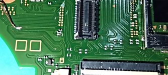
If necessary, you could use 3.3V from the back pcb.
Back pcb
Front Pcb
I tore apart the right pad from RST. Are bothe pads needed for the console to work properly?? V1 switch
I keep getting the Error code "RST not connected" (It happened also before I tore off the pad). I habe changed the wire, cleaned every Flux residue, but nothing, it keeps blinking just twice
I keep getting the Error code "RST not connected" (It happened also before I tore off the pad). I habe changed the wire, cleaned every Flux residue, but nothing, it keeps blinking just twice
Attachments
Last edited by Myst0gan,
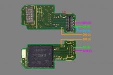
Unfortunately some pin are needed.I tore apart the right pad from RST. Are bothe pads needed for the console to work properly??
That green one is CMD line.
The pale red one i don't know, don't have time to track.
The gray and black are GND.
Magenta : Dat0
Cyan: Clk
Blue: RST (emmc doesn't use it at all)
Bright Red: 3.3V
Yellow: 1.8V
Do you know where the SDA and SCL pads are on v1 switch?? I don't see the testing points, like it's shown on the guide.Unfortunately some pin are needed.
View attachment 408035
That green one is CMD line.
The pale red one i don't know, don't have time to track.
The gray and black are GND.
Magenta : Dat0
Cyan: Clk
Blue: RST (emmc doesn't use it at all)
Bright Red: 3.3V
Yellow: 1.8V
If the nand doesn't use rst, then I'll leave it
Attachments
I've no idea either.Do you know where the SDA and SCL pads are on v1 switch?? I don't see the testing points, like it's shown on the guide.
If the nand doesn't use rst, then I'll leave it
You could track it yourself if you really want to pursue that. The necessart file are already shared on the sibling thread for pcbscan, etc. Track the line in v2 it will goes to what pin, then compare to the pcbscan for v1.
In my experience v1 is the fastest glitch than any other type.
I dont think anyone will need the sda/scl method especially for v1.
FYI, those sda/scl are unstable, use it if theres no other option.
I dont think anyone use it though in recent days.
Why 200??The only console where i used sda/scl, i have problems on it freezing in CFW and unable to boot OFW. I had to put 200 ohm resistors on dat0 and cmd to work. Coincidence? Maybe
Do you know where sda and scl points are??
Post automatically merged:
Just tried, both boards are completely different on sda/scl... they go to different components, which aren't present on v1I've no idea either.
You could track it yourself if you really want to pursue that. The necessart file are already shared on the sibling thread for pcbscan, etc. Track the line in v2 it will goes to what pin, then compare to the pcbscan for v1.
In my experience v1 is the fastest glitch than any other type.
I dont think anyone will need the sda/scl method especially for v1.
FYI, those sda/scl are unstable, use it if theres no other option.
I dont think anyone use it though in recent days.
Last edited by Myst0gan,
So I have a RP2040 Tiny and everything works boots into CFW and OFW but I get no glitch led lights. I only get a led light on firmware 2.5+unlock but it stays solid green and wont turn off.
Any help?
Any help?

It's a sh*tty clone. Flash it with v2.67 for example, the LED will be always off, but who cares if it works, right? Though in the future you won't be able to troubleshoot the error codes if needed.So I have a RP2040 Tiny and everything works boots into CFW and OFW but I get no glitch led lights. I only get a led light on firmware 2.5+unlock but it stays solid green and wont turn off.
Any help?
Otherwise, buy an original directly from Waveshare.
Yea I regret buying it to save a couple of bucks. Thought everything would work the same.It's a sh*tty clone. Flash it with v2.67 for example, the LED will be always off, but who cares if it works, right? Though in the future you won't be able to troubleshoot the error codes if needed.
Otherwise, buy an original directly from Waveshare.
Similar threads
- Replies
- 8
- Views
- 1K
- Replies
- 8
- Views
- 3K
- Replies
- 3
- Views
- 688
- Replies
- 10
- Views
- 2K
- Replies
- 1
- Views
- 2K
Site & Scene News
New Hot Discussed
-
-
25K views
Nintendo Switch firmware update 18.0.1 has been released
A new Nintendo Switch firmware update is here. System software version 18.0.1 has been released. This update offers the typical stability features as all other... -
19K views
The first retro emulator hits Apple's App Store, but you should probably avoid it
With Apple having recently updated their guidelines for the App Store, iOS users have been left to speculate on specific wording and whether retro emulators as we... -
19K views
Delta emulator now available on the App Store for iOS
The time has finally come, and after many, many years (if not decades) of Apple users having to side load emulator apps into their iOS devices through unofficial...by ShadowOne333 96 -
19K views
TheFloW releases new PPPwn kernel exploit for PS4, works on firmware 11.00
TheFlow has done it again--a new kernel exploit has been released for PlayStation 4 consoles. This latest exploit is called PPPwn, and works on PlayStation 4 systems... -
16K views
Nintendo takes down Gmod content from Steam's Workshop
Nintendo might just as well be a law firm more than a videogame company at this point in time, since they have yet again issued their now almost trademarked usual...by ShadowOne333 120 -
16K views
Nintendo officially confirms Switch successor console, announces Nintendo Direct for next month
While rumors had been floating about rampantly as to the future plans of Nintendo, the President of the company, Shuntaro Furukawa, made a brief statement confirming... -
14K views
A prototype of the original "The Legend of Zelda" for NES has been found and preserved
Another video game prototype has been found and preserved, and this time, it's none other than the game that spawned an entire franchise beloved by many, the very...by ShadowOne333 31 -
12K views
Anbernic reveals specs details of pocket-sized RG28XX retro handheld
Anbernic is back with yet another retro handheld device. The upcoming RG28XX is another console sporting the quad-core H700 chip of the company's recent RG35XX 2024... -
11K views
Name the Switch successor: what should Nintendo call its new console?
Nintendo has officially announced that a successor to the beloved Switch console is on the horizon. As we eagerly anticipate what innovations this new device will... -
11K views
Nintendo Switch Online adds two more Nintendo 64 titles to its classic library
Two classic titles join the Nintendo Switch Online Expansion Pack game lineup. Available starting April 24th will be the motorcycle racing game Extreme G and another...
-
-
-
238 replies
Name the Switch successor: what should Nintendo call its new console?
Nintendo has officially announced that a successor to the beloved Switch console is on the horizon. As we eagerly anticipate what innovations this new device will...by Costello -
207 replies
Nintendo officially confirms Switch successor console, announces Nintendo Direct for next month
While rumors had been floating about rampantly as to the future plans of Nintendo, the President of the company, Shuntaro Furukawa, made a brief statement confirming...by Chary -
120 replies
Nintendo takes down Gmod content from Steam's Workshop
Nintendo might just as well be a law firm more than a videogame company at this point in time, since they have yet again issued their now almost trademarked usual...by ShadowOne333 -
97 replies
The first retro emulator hits Apple's App Store, but you should probably avoid it
With Apple having recently updated their guidelines for the App Store, iOS users have been left to speculate on specific wording and whether retro emulators as we...by Scarlet -
96 replies
Delta emulator now available on the App Store for iOS
The time has finally come, and after many, many years (if not decades) of Apple users having to side load emulator apps into their iOS devices through unofficial...by ShadowOne333 -
82 replies
Nintendo Switch firmware update 18.0.1 has been released
A new Nintendo Switch firmware update is here. System software version 18.0.1 has been released. This update offers the typical stability features as all other...by Chary -
80 replies
TheFloW releases new PPPwn kernel exploit for PS4, works on firmware 11.00
TheFlow has done it again--a new kernel exploit has been released for PlayStation 4 consoles. This latest exploit is called PPPwn, and works on PlayStation 4 systems...by Chary -
74 replies
New static recompiler tool N64Recomp aims to seamlessly modernize N64 games
As each year passes, retro games become harder and harder to play, as the physical media begins to fall apart and becomes more difficult and expensive to obtain. The...by Chary -
74 replies
"Nintendo World Championships: NES Edition", a new NES Remix-like game, launching July 18th
After rumour got out about an upcoming NES Edition release for the famed Nintendo World Championships, Nintendo has officially unveiled the new game, titled "Nintendo...by ShadowOne333 -
71 replies
DOOM has been ported to the retro game console in Persona 5 Royal
DOOM is well-known for being ported to basically every device with some kind of input, and that list now includes the old retro game console in Persona 5 Royal...by relauby
-
Popular threads in this forum
General chit-chat
-
 BakerMan
Loading…I rather enjoy a life of taking it easy. I haven't reached that life yet though.
BakerMan
Loading…I rather enjoy a life of taking it easy. I haven't reached that life yet though. -
 Psionic Roshambo
Loading…
Psionic Roshambo
Loading…