

You are using an out of date browser. It may not display this or other websites correctly.
You should upgrade or use an alternative browser.
You should upgrade or use an alternative browser.
Staff Posts
Recent threadmarks
sharing files
Important Posts
Recent threadmarks
Firmwares


Single or both bridged is fine since they are already bridged.Do i need to solder to both points of each connection or are they connected internally?
- Joined
- Sep 2, 2020
- Messages
- 1,350
- Trophies
- 0
- Age
- 39
- Location
- TORONTO
- Website
- form.jotform.com
- XP
- 2,283
- Country

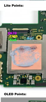
Wrong 3.3V pointOLED RP2040 install, First time i have had an issue but also the first oled install. I have done dual mosfet. When battery is plugged in i get blue LED then goes off. And then when i then click power button no LED shows and OFW boots. I have permanent DAT0 installed soldered under emmc. what have a missed?
edit:
I have the same problem, I have 2 mosfets connected and when I connect the battery only the peak turns on and the light turns off. What is the solution to this problem in Oled models?

Hey guys
When i go to console Info on Hekate it says eMMC is runing on lower mode but is still 400Mb. When i go out and revisit the console info it drops to 200 mb. The OFW seems also not starting. CFW is working. Any idea what the issue could be?
Maybe the wires are kinda long on a part somehow?
EDIT: Could update it through payload picofly_toolkit. Now im facing the next issue FML.Quick question guys. My Pico zero has already detached usb c and buttons. I was on fw 2.5 i think. I think i should update, when there is a new firmware, like 2.67 right now, for my pico zero, but how can i do that? resolder usb c?
When i go to console Info on Hekate it says eMMC is runing on lower mode but is still 400Mb. When i go out and revisit the console info it drops to 200 mb. The OFW seems also not starting. CFW is working. Any idea what the issue could be?
Maybe the wires are kinda long on a part somehow?

Bridging those points is kinda wasting time, its harder than to directly solder to it.Do i need to solder to both points of each connection or are they connected internally?
Just solder to it and test the strength by swinging/moving it - the cable 90 degrees left right up down for maybe 5 times, if by then the jointed point doesnt break then it should be safe to leave it like that and proceed.
I just want to make sure I'm understanding this correctly. You remove the 470ohm resistors from the board, bridge those 3 points with solder, and then add the 47ohm resistors to the solder joints like the regular 2040-zero chip? Are you using the 0805 size resistors?0201
Post automatically merged:
Replace 470ohm with 47ohm, successful
Thanks so much for your help.
Thats what I would assume, you could also just replace them with 47ohm 0201, but they are annoyingly tinyI just want to make sure I'm understanding this correctly. You remove the 470ohm resistors from the board, bridge those 3 points with solder, and then add the 47ohm resistors to the solder joints like the regular 2040-zero chip? Are you using the 0805 size resistors?
Thanks so much for your help.
Bridging those points is kinda wasting time, its harder than to directly solder to it.
Just solder to it and test the strength by swinging/moving it - the cable 90 degrees left right up down for maybe 5 times, if by then the jointed point doesnt break then it should be safe to leave it like that and proceed.
I highly advise against stressing your cables that much, metal doesn't like being bent back and forth.
To me, if the joint survives my IPA\Q-tip cleaning, it's soldered well enough.
Edit for redundancy
Last edited by LogicalMadness,

Has anybody tried using different resistor values? I've just run out of 47 Ohm, but have plenty of 27, 20 and 68 Ohm.
Maybe I could get away with 68 on the dat0 and CMD line and parallel 68 on the CLK?
I'm assuming these resistors are just for impedence matching?
Maybe I could get away with 68 on the dat0 and CMD line and parallel 68 on the CLK?
I'm assuming these resistors are just for impedence matching?
Hey, first time soldering here and I had a few questions;
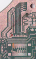
I made an oopsie on the M92T36 chip and knocked off a few components and, while waiting for replacements, I decided to remove soldering points as my switch is completely dead (which I guess can also be related to 2 capacitors being knocked off around the M92T36).
But anyway, while checking for continuity, I have realized that the RST soldering point (marked in ORANGE) on a HAD-CPU-10 board is not bridging with the resistor right beside it (marked in RED) and then noticed that I accidentally scratched off the upper RST pad that bridges the two. However, while checking the lower RST pad and determining that it's still usable as a soldering point (by checking continuity between it and the second upper pin from the left of the connector), here comes my question:
Would it work to bridge the resistor and the lower RST pad with solder and am I safe from the scratched traces with just kapton tape?
Attachments
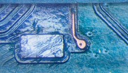
this looked neat, should try this next , less headache lolHad some time to play around with MOSFETs in order to find a way for a quicker soldering to the SoC.
No science here, just a silly test that I wanted to share with you.
- basically, got a transparent plastic as a base on which I fixed the 2 MOSFETs with a tiny bit of superglue (from underneath). This way they won't move and make the soldering easier.
- soldered the Source and 2 Gate wires. Afterwards bridged the 2 Gates, so there'll be only one wire that goes to the Pico and used some UV mask to isolate the soldering point.
- now these "flying" MOSFETs can be taken by the plastic base and fixed easily nearby the SoC, and afterwards anchored well with Drain wires + more UV mask.
View attachment 370497
Post automatically merged:
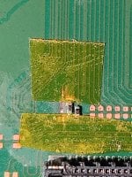
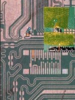
hey guys, to grind and reveal this part here on oled do we need to use mini grinder? or its possible scrape it just only using scalpel ?
Attachments
Last edited by blackheartme,
- Joined
- Sep 2, 2020
- Messages
- 1,350
- Trophies
- 0
- Age
- 39
- Location
- TORONTO
- Website
- form.jotform.com
- XP
- 2,283
- Country
You need to have A,B,C points join together no matter how.Hey, first time soldering here and I had a few questions;
I made an oopsie on the M92T36 chip and knocked off a few components and, while waiting for replacements, I decided to remove soldering points as my switch is completely dead (which I guess can also be related to 2 capacitors being knocked off around the M92T36).
But anyway, while checking for continuity, I have realized that the RST soldering point (marked in ORANGE) on a HAD-CPU-10 board is not bridging with the resistor right beside it (marked in RED) and then noticed that I accidentally scratched off the upper RST pad that bridges the two. However, while checking the lower RST pad and determining that it's still usable as a soldering point (by checking continuity between it and the second upper pin from the left of the connector), here comes my question:
Would it work to bridge the resistor and the lower RST pad with solder and am I safe from the scratched traces with just kapton tape?
Cant tell if you still have trace left on top of the pads where A and B used to bridge together, but I don't think any jumper would make more difficult.
Post automatically merged:
good enough with just scalpelor its possible scrape it just only using scalpel ?
Attachments
Last edited by jkyoho,
I always use scalpelthis looked neat, should try this next , less headache lol
Post automatically merged:
hey guys, to grind and reveal this part here on oled do we need to use mini grinder? or its possible scrape it just only using scalpel ?
Yes. It seems some users are reporting you have to remove the 470ohm resistors on the board and replace them with the 47ohm. If this chip was made with the switch in mind then they accidentally used 470 instead of 47.
I'm waiting on mine so I can't confirm myself, but it seems to work with that little modification
470 means 47ohm/47RYes. It seems some users are reporting you have to remove the 470ohm resistors on the board and replace them with the 47ohm. If this chip was made with the switch in mind then they accidentally used 470 instead of 47.
I'm waiting on mine so I can't confirm myself, but it seems to work with that little modification
https://kiloohm.info/smd3-resistor/470
If they use 470ohm/470R
Then the correct resistor smd should "4700"
https://kiloohm.info/smd4-resistor/4700#:~:text=Standard EIA Decade Values Table - decade 100 to 1000 Ω&text=The 4 digit SMD resistor,hundred and seventy Ohms resistance.
4700 stands for 470ohm
470 stands for 47ohm
Got PicoFly on 2.67 with firmware 15.0.1. Updated to 16.0.2 using DayBreak after booting to CFW SysNand. Enabled Fat + Fat32 and kept all setting. during Daybreak update.
Restarted after update completed into hekate and tried rebooting to OFW. Got a black screen, no logo. Tried booting with volume +/- held, same black screen. Also took out sd card then pressed volume +/-.
Had to boot switch after disconnecting cpu wire on pico to get to OFW. Then reconnected cpu wire and can boot fine to OFW.
Checked the pico toolbox and the info said Fuse 1. I think it was 0 before.
Why didn't the switch boot to OFW after updating? Don't want to have to disconnect the cpu wire every time it's updated.
TIA
Thank you for the answer, somehow point A totally escaped my mind of being any importance.You need to have A,B,C points join together no matter how.
Cant tell if you still have trace left on top of the pads where A and B used to bridge together, but I don't think any jumper would make more difficult.
Would a small box cutter do to expose the trace?

With PicoFly you're suppose to update OFW via official way, through the Settings. EmuMMC can be updated with DayBreak, and remember to update the Atmo & other files on the SD so it can work with the new FW version (at least it has worked for me in the past).Got PicoFly on 2.67 with firmware 15.0.1. Updated to 16.0.2 using DayBreak after booting to CFW SysNand. Enabled Fat + Fat32 and kept all setting. during Daybreak update.
Restarted after update completed into hekate and tried rebooting to OFW. Got a black screen, no logo. Tried booting with volume +/- held, same black screen. Also took out sd card then pressed volume +/-.
Had to boot switch after disconnecting cpu wire on pico to get to OFW. Then reconnected cpu wire and can boot fine to OFW.
Checked the pico toolbox and the info said Fuse 1. I think it was 0 before.
Why didn't the switch boot to OFW after updating? Don't want to have to disconnect the cpu wire every time it's updated.
TIA
Note for the future: if you use "DIY transistors" for the glitch, I suppose you didn't include a pull-down resistor, so disconnecting the CPU pin is not enough, you need to disconnect the Source and/or Drain from the MOSFETs, otherwise some black smoke can come out from those transistors.
Similar threads
- Replies
- 5
- Views
- 3K
- Replies
- 2
- Views
- 900
- Replies
- 42
- Views
- 7K
Site & Scene News
New Hot Discussed
-
-
20K views
Majora’s Mask PC port 2Ship2Harkinian gets its first release
After several months of work, the Harbour Masters 64 team have released their first public build of 2Ship2Harkinian, a feature-rich Majora's Mask PC port. This comes... -
19K views
Mario Builder 64 is the N64's answer to Super Mario Maker
With the vast success of Super Mario Maker and its Switch sequel Super Mario Maker 2, Nintendo fans have long been calling for "Maker" titles for other iconic genres... -
18K views
Modders hint at potential kernel exploit hack for Xbox One consoles
It's been a while since Microsoft released the Xbox One, and despite its age, there haven't been any reliable softmod methods to hack the console. Until now. A post... -
17K views
The founder of Oculus is releasing a $199 FPGA Game Boy system
Palmer Luckey is known for his pursuits into the world of virtual reality, having founded Oculus and designed the Rift VR headset. Prior to the $2 billion dollar... -
14K views
Nintendo takes down the Breath of the Wild randomizer mod from Gamebanana
Another day, another Nintendo DMCA takedown against fan-made content. Just a few minutes ago, Nintendo issued a DMCA takedown notice against a widely known and...by ShadowOne333 104 -
14K views
The Kingdom Hearts games are coming to Steam
After a little more than three years of exclusivity with the Epic Games Store, Square Enix has decided to bring their beloved Kingdom Hearts franchise to Steam. The... -
12K views
Select PlayStation 2 games are coming to PlayStation 5
Sony is once more attempting to reintroduce players to their older library of games by re-releasing classic PlayStation 2 titles onto the PlayStation Store. During... -
11K views
Skyward Sword HD randomizer announced with release date and trailer
Skyward Sword is a divisive title in the Zelda series. Hailed with praise at launch with a 93 Metacritic average, the game since received criticism for the... -
10K views
PlayStation State of Play May 2024 showcase - God of War: Ragnarok coming to PC
The latest State of Play is here. This is PlayStation's Summer showcase, providing updates to new updates on upcoming games and brand new reveals. The 35-minute... -
9K views
Nintendo acquires company behind Mortal Kombat 1 and Hogwarts Legacy ports on Switch, "Shiver Entertainment Inc."
Nintendo is having quite the successful console generation with the Nintendo Switch, and with the follow-up to the Switch already on the horizon confirmed by...by ShadowOne333 48
-
-
-
169 replies
The founder of Oculus is releasing a $199 FPGA Game Boy system
Palmer Luckey is known for his pursuits into the world of virtual reality, having founded Oculus and designed the Rift VR headset. Prior to the $2 billion dollar...by Chary -
118 replies
Modders hint at potential kernel exploit hack for Xbox One consoles
It's been a while since Microsoft released the Xbox One, and despite its age, there haven't been any reliable softmod methods to hack the console. Until now. A post...by Chary -
108 replies
Majora’s Mask PC port 2Ship2Harkinian gets its first release
After several months of work, the Harbour Masters 64 team have released their first public build of 2Ship2Harkinian, a feature-rich Majora's Mask PC port. This comes...by Scarlet -
104 replies
Nintendo takes down the Breath of the Wild randomizer mod from Gamebanana
Another day, another Nintendo DMCA takedown against fan-made content. Just a few minutes ago, Nintendo issued a DMCA takedown notice against a widely known and...by ShadowOne333 -
91 replies
The Kingdom Hearts games are coming to Steam
After a little more than three years of exclusivity with the Epic Games Store, Square Enix has decided to bring their beloved Kingdom Hearts franchise to Steam. The...by Chary -
79 replies
Select PlayStation 2 games are coming to PlayStation 5
Sony is once more attempting to reintroduce players to their older library of games by re-releasing classic PlayStation 2 titles onto the PlayStation Store. During...by Chary -
66 replies
Mario Builder 64 is the N64's answer to Super Mario Maker
With the vast success of Super Mario Maker and its Switch sequel Super Mario Maker 2, Nintendo fans have long been calling for "Maker" titles for other iconic genres...by Scarlet -
64 replies
PlayStation State of Play May 2024 showcase - God of War: Ragnarok coming to PC
The latest State of Play is here. This is PlayStation's Summer showcase, providing updates to new updates on upcoming games and brand new reveals. The 35-minute...by Chary -
62 replies
Summer Game Fest 2024 coverage - Civilization VII announced
E3 may be gone, but it's not forgotten, as the trend of a massive Summer video game showcase still lives on in the form of the Summer Game Fest. Promising two hour of...by Chary -
54 replies
Doom for SNES full source code released by former Sculptured Software employees
The complete source code for the Super Nintendo Entertainment System (SNES) version of Doom has been released on archive.org. Although some of the code was partially...by shaunj66
-