Hacking Hardware Picofly - a HWFLY switch modchip

FreeLander

Well-Known Member
Member
Joined
Apr 6, 2023
Messages
350
Trophies
0
Age
35
XP
467
Country
United States
nice, Iam using 100 ohm on data0 having slow glitch (4-5s most, rarely 2-3sec).Will switch back and see
I should do the same. In that video, it glitched fast, but I tried it a couple more times and it took an exact MINUTE. I think I'll double the 47s on dat0 as well.
Post automatically merged:

This brings up a question I’ve been meaning to ask. What sets a fast-glitching install from a long one? Is it related to how skillful the modchip was installed?
 
Last edited by FreeLander,

Danook28

Well-Known Member
Member
Joined
Jul 17, 2018
Messages
496
Trophies
0
Age
34
XP
1,032
Country
Oman
bed-time.gif
That is the new chip no need resistor mate.
 

RTXbothunter

Member
Newcomer
Joined
Apr 23, 2023
Messages
5
Trophies
0
Age
28
XP
22
Country
Dominican Republic
Hi everyone i have an issue with a v1 patch i always get **(tow short yellow lights) i change and wires 3 time, change the rp2040, and the flex 2 times, y try with firmware 2.6 and 2.7, i dont know what really try to have runing
 
  • Like
Reactions: Danook28

Danook28

Well-Known Member
Member
Joined
Jul 17, 2018
Messages
496
Trophies
0
Age
34
XP
1,032
Country
Oman
Hi everyone i have an issue with a v1 patch i always get **(tow short yellow lights) i change and wires 3 time, change the rp2040, and the flex 2 times, y try with firmware 2.6 and 2.7, i dont know what really try to have runing
Your wiers short??? All point read good????
 

Takezo-San

Well-Known Member
Member
Joined
May 3, 2023
Messages
261
Trophies
0
Age
39
XP
348
Country
Seychelles
That is the new chip no need resistor mate.
You really think I would ask that question? Tut tut tut

0b49bc49ac578eb8500be1caae55788a.gif

Post automatically merged:

This brings up a question I’ve been meaning to ask. What sets a fast-glitching install from a long one? Is it related to how skillful the modchip was installed?
I'm sure I read the length of wires makes a difference. This is a timing mod and exploit after all. Plus manufacturer of the nand chip.
 
Last edited by Takezo-San,

Seco_Gobbo2

Member
Newcomer
Joined
Jul 6, 2023
Messages
15
Trophies
0
Age
35
XP
209
Country
Brazil
Hello everybody.

I saw some installation posts here with only one mosfet on the back of the board, but only on oled models.

Is it possible to do this installation with only one mosfet in the V1 models?
 

abal1000x

Well-Known Member
Member
Joined
Jun 5, 2022
Messages
1,062
Trophies
0
XP
1,367
Country
Gaza Strip
Hello everybody.

I saw some installation posts here with only one mosfet on the back of the board, but only on oled models.

Is it possible to do this installation with only one mosfet in the V1 models?
You could do it to all type of switch.
The D mosfet are connected to the 1V power output from Max77620.
 
  • Like
Reactions: Seco_Gobbo2

Takezo-San

Well-Known Member
Member
Joined
May 3, 2023
Messages
261
Trophies
0
Age
39
XP
348
Country
Seychelles
Hello everybody.

I saw some installation posts here with only one mosfet on the back of the board, but only on oled models.

Is it possible to do this installation with only one mosfet in the V1 models?
Look back properly. People have shown it done with Lite too. Not only Oled.
 

roxzii

Well-Known Member
Newcomer
Joined
Nov 11, 2022
Messages
47
Trophies
0
Age
27
XP
248
Country
Portugal
Yes Ammeter to check if there is power draw - also check your lcd connector for damaged pins
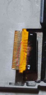
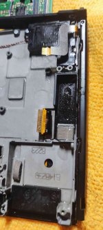
Thanks for this, I never thought the lcd connector would be the problem since I had the no sd screen and blue screen before. But I verified the soldering on the SP1 pads and a wire had come loose. Fixed that, reattached picofly and actually got successful glitch (blue then short yellow), but nothing on screen. I guess after removing and reattaching the board to diagnose I seem to have damaged the connector, maybe with the tweezers. I tried the fiber glass brush but still no continuity on the multimeter.

Two questions:

Since the pico manages to glitch as far as I can tell, how dead may the console be? (Checked all the caps around both chips you mentioned and found no shorts).

And also, it's not possible for a bad connector to cause a blue screen, right? It would either display or not display, not throw an error, right?

EDIT: Third question, I just found out that if that ribbon is gone, so is the whole lcd. Any way to use jumper wires to fix that scratch?
 

Attachments

  • Screenshot_20230710_063117_Discord.jpg
    Screenshot_20230710_063117_Discord.jpg
    80.3 KB · Views: 27
  • IMG_20230710_062831.jpg
    IMG_20230710_062831.jpg
    124.8 KB · Views: 27
Last edited by roxzii,

abal1000x

Well-Known Member
Member
Joined
Jun 5, 2022
Messages
1,062
Trophies
0
XP
1,367
Country
Gaza Strip
Thanks. When do you say ok this one needs a two? If persistent with check mosfet error and boots to OFW?
I've prove by data that, adding mosfet or changing the resistor value, wont affect the glitching time.

So just like what i always said in the beginning, 1 mosfet is enough.

If the glitch didn't happened, than problem lay on other aspect.
 

cowboy619

Well-Known Member
Member
Joined
Jan 22, 2014
Messages
248
Trophies
1
Age
40
Location
Cape Town, Western Cape
XP
1,810
Country
Thanks for this, I never thought the lcd connector would be the problem since I had the no sd screen and blue screen before. But I verified the soldering on the SP1 pads and a wire had come loose. Fixed that, reattached picofly and actually got successful glitch (blue then short yellow), but nothing on screen. I guess after removing and reattaching the board to diagnose I seem to have damaged the connector, maybe with the tweezers. I tried the fiber glass brush but still no continuity on the multimeter.

Two questions:

Since the pico manages to glitch as far as I can tell, how dead may the console be? (Checked all the caps around both chips you mentioned and found no shorts).

And also, it's not possible for a bad connector to cause a blue screen, right? It would either display or not display, not throw an error, right?

EDIT: Third question, I just found out that if that ribbon is gone, so is the whole lcd. Any way to use jumper wires to fix that scratch?
Most of the time if you getting black screens then the connector is damaged. Check the connector on the board the ribbon is not that clear so cant see - maybe its glitching but we cant see cos the screen error
 
  • Like
Reactions: roxzii

Takezo-San

Well-Known Member
Member
Joined
May 3, 2023
Messages
261
Trophies
0
Age
39
XP
348
Country
Seychelles
Thanks for this, I never thought the lcd connector would be the problem since I had the no sd screen and blue screen before. But I verified the soldering on the SP1 pads and a wire had come loose. Fixed that, reattached picofly and actually got successful glitch (blue then short yellow), but nothing on screen. I guess after removing and reattaching the board to diagnose I seem to have damaged the connector, maybe with the tweezers. I tried the fiber glass brush but still no continuity on the multimeter.

Two questions:

Since the pico manages to glitch as far as I can tell, how dead may the console be? (Checked all the caps around both chips you mentioned and found no shorts).

And also, it's not possible for a bad connector to cause a blue screen, right? It would either display or not display, not throw an error, right?

EDIT: Third question, I just found out that if that ribbon is gone, so is the whole lcd. Any way to use jumper wires to fix that scratch?
If the pico has glitches successfully then that's a good sign the switch is good however the next step is to check and fix that lcd connector.

I will be working on a switch lite myself that has a blue screen and then no screen. Found a burnt pin on the lcd connector. Will attempt fix and let you know if blue screen is gone or if that lcd connector removes no picture.

I will say, the real test is to get rid of blue or black screen. Then see the no sd pico logo and then....check with sd card if it boots into hekate. Ways to go but so far, good work 👍🏻
 
  • Like
Reactions: roxzii

twins333

Well-Known Member
Newcomer
Joined
May 30, 2023
Messages
86
Trophies
0
XP
311
Country
Afghanistan
I've prove by data that, adding mosfet or changing the resistor value, wont affect the glitching time.

So just like what i always said in the beginning, 1 mosfet is enough.

If the glitch didn't happened, than problem lay on other aspect.
Also use thinner enamel wires on oleds, except for the 3V and gnd. Thicker wires can (and have) result(ed) in unsuccessful glitches for oleds.
 
  • Haha
Reactions: cowboy619

Quezacotl

Well-Known Member
Newcomer
Joined
Aug 12, 2020
Messages
69
Trophies
0
Age
37
XP
235
Country
Finland
Hello!
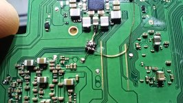
I tried the backside FET method on OLED, but all i get is this error:
"CPU always reach BCT check (no glitch reaction, checkmosfet)"
I'm using the IRFHS8242. Already tried another FET incase it was broken but still same.
Using fw 2.73.

Any suggestions?
 

Attachments

  • IMG_20230710_134701.jpg
    IMG_20230710_134701.jpg
    406.7 KB · Views: 37

abal1000x

Well-Known Member
Member
Joined
Jun 5, 2022
Messages
1,062
Trophies
0
XP
1,367
Country
Gaza Strip
Hello!
I tried the backside FET method on OLED, but all i get is this error:
"CPU always reach BCT check (no glitch reaction, checkmosfet)"
I'm using the IRFHS8242. Already tried another FET incase it was broken but still same.
Using fw 2.73.

Any suggestions?
The S part need more solder.
 

deeps

Well-Known Member
Member
Joined
Jul 3, 2007
Messages
450
Trophies
1
XP
1,245
Country
Also use thinner enamel wires on oleds, except for the 3V and gnd. Thicker wires can (and have) result(ed) in unsuccessful glitches for oleds.

No. Quit bullshitting, thanks.
Post automatically merged:

Hello!
I tried the backside FET method on OLED, but all i get is this error:
"CPU always reach BCT check (no glitch reaction, checkmosfet)"
I'm using the IRFHS8242. Already tried another FET incase it was broken but still same.
Using fw 2.73.

Any suggestions?

I would measure the G/cpu point on the rp2040 and make sure it isn't shorted to ground somehow.
 
  • Like
Reactions: Takezo-San

Site & Scene News

Popular threads in this forum

General chit-chat
Help Users
    K3Nv2 @ K3Nv2: https://youtube.com/shorts/BiY0vNuu1eg?si=0nwmSHWeLkfcJJ__