Good afternoon I ran into an interesting problem.
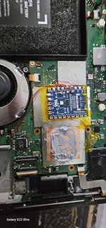
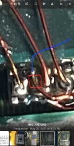
Switch OLED (FW 2.67). DAT0 adapter, the contact is well soldered. Diode test value 0.800v. Same value when pin is already soldered to rp2040 Zero (wire 0.1mm).
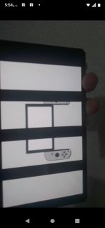
Approximately once a week at the next reboot of the switch, I get the yellow color of the LED and it loads only in OFW.
I check the contact to the ground in the DAT0 diode mode and I already get about 1.500v. Strange.
I just unplug the DAT0 wire from rp2040 and immediately solder it back. Immediately a diode test shows the correct 0.800v. Everything works fine again until the next similar event.
I tried to change the wire from the adapter to rp2040 to a thinner one, I also changed the resistor (the correct one is 47Ohm), but the problem repeats regularly.
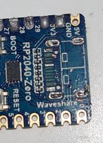
Some kind of mysticism, any ideas why this happens and how I could avoid this in the future? Can I replace the rp2040 board
what dat0 adapter are u using ?
is it set properly ?.
not sure what the issue is but i would get rid of that dat0 adapter and eather use a 4 anchor or set a perm adapter and reball the emmc


 10.17.21.jpg")