


Could it have been working fine three days before if it's the wrong soldering?must check it
Post automatically merged:
use other soldering point work better
Post automatically merged:
looks like wrong soldering job
You are using an out of date browser. It may not display this or other websites correctly.
You should upgrade or use an alternative browser.
You should upgrade or use an alternative browser.
Staff Posts
Recent threadmarks
sharing files
Important Posts
Recent threadmarks
Firmwares
it's not that complicated as you describing the whole install...if you want to uninstall just reverse the process witch is about 30 sec...i dont know what you have in mind...
Post automatically merged:
Come on if you want to replace the fan or whatever you just unscrew the shield and lift a little bit the rp2040…I never said it was complicated, I basically just said it 'adds unneeded steps', and you're forgetting about the time to reinstall it.
Think your fan is never going to die? Never want to replace the thermal paste again? Sure hope you only charge with an official charger and never mess up plugging it in.
I can’t understand why you make it look like a problem

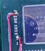
Can you give a link(or image) of where these other soldering points are?must check it
Post automatically merged:
use other soldering point work better
Post automatically merged:
looks like wrong soldering job


yes, its a toshiba but toshiba is supportedI've fully resolder, make data wires shorter, but still got blue->pink(or purple?). After soldering GRB/RGB points together pico shows blue->green lights (and starts ofw with 2101-0001 error). Also, can someone say do my switch have toshiba emmc or not?

I was soldring all point on v1 nintendo switch on motherboard only 3v3 on nand sd chip i tern on it was blue then red i soldering GND it was Disconnect after that blue then green in dock put nothing show dock blinking. The lite after try see what boot on tv. Then it is back purpel. No more tern on.i think some thing wrong on sd nand me be.
Last edited by Danook28,

Yes it can br cold solder , purple screen it problem with EMMCCould it have been working fine three days before if it's the wrong soldering?

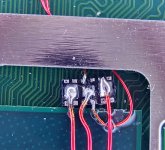
yes, I noticed this problem at the assembly stage and fixed it, it's just that this is the first photo, 50 ohm resistors, other people put them, they also work like 47Your 50 (49.9) ohm resistors threw me a little bit, but those should be alright, considering you were booting. Is it possible that your wire attached to the resistor on pin 26 is intermittently hitting the ground pad of your removed button, and foiling the picofly glitch?
I've just received the resistors in the mail and promptly replaced the old resistors with them.must check it
51R (both 0603/0805 package) measure at about 50.2-50.4Ohms (sample size: 20 resistors) and the glitch times are expectedly just as good as with 100R in parallel and better than with the 47R resistors with the aforementioned SKHynix 64GB emmc.
I'd love to hear from rehius what his thoughts are on that matter though, before something goes electrically haywire in the long run, as I'd rather not fry my switch by assuming things.
Also: Pics of the installation because everyone and their dog seems to do it.

Fluffy bits were from q-tips, before I cleaned up the flux, everything relevant was afterwards gently tacked down using 3D printing resin (The solder mask I got in China a few years ago wasn't really reacting to UV light anymore. Ew.).
Attachments
As far as I know purple screen mostly bad CMD point or blown CMD resistor.Yes it can br cold solder , purple screen it problem with EMMC

When the purple screen happened, did you use emummc or sysmmc?Greetings! Another problem. Yesterday my switch was working fine. Today I turn on - a purple screen. After the reboot, it was possible to start the drain, but after a couple of seconds an error occurred. Through time it is possible to get into the recovery menu, even did a reset to the factory settings. But still purple screen or error.
View attachment 370857
View attachment 370858
After another reboot i have this:
View attachment 370868
But then:
View attachment 370869
Yes it can br cold solder , purple screen it problem with EMMC
As far as I know purple screen mostly bad CMD point or blown CMD resistor.
It seems that the problem was really in the resistor, but I don’t know which one, so I replaced everything and it helped. At least for a while)When the purple screen happened, did you use emummc or sysmmc?

Is it charging?I've fully resolder, make data wires shorter, but still got blue->pink(or purple?). After soldering GRB/RGB points together pico shows blue->green lights (and starts ofw with 2101-0001 error). Also, can someone say do my switch have toshiba emmc or not?
Going through the thread it seems that in most cases the error you are seeing is caused by faulty M92T36 chip.
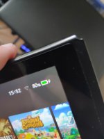
Yes, percentage goes upIs it charging?
Going through the thread it seems that in most cases the error you are seeing is caused by faulty M92T36 chip.
upd: forgot to mention - error disappeared after I solder ground to another point
Attachments
So @Haseo13 was right, using different soldering points fixed the issue?Yes, percentage goes up
upd: forgot to mention - error disappeared after I solder ground to another point
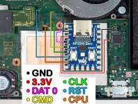
At first I tried to solder on the one side of emmc and also resolder ground, but it didn't help with pico, same led colors. Will try different points later and post results. Also, is it fine if I solder on board only D0, CMD and CLK, leaving power and RST on emmc?So @Haseo13 was right, using different soldering points fixed the issue?
Yes, you can mix-and-match the soldering points as you see fit for your installation.At first I tried to solder on the one side of emmc and also resolder ground, but it didn't help with pico, same led colors. Will try different points later and post results. Also, is it fine if I solder on board only D0, CMD and CLK, leaving power and RST on emmc?
It seems that the problem was really in the resistor, but I don’t know which one, so I replaced everything and it helped. At least for a while)
Its not clear for me. So You replace the CMD resistor and now its working?
Anyway i'm almost sure purple screen is mostly caused by blown cmd resistor.
I replaced all threeIts not clear for me. So You replace the CMD resistor and now its working?
Anyway i'm almost sure purple screen is mostly caused by blown cmd resistor.
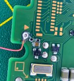
Also, when soldering to board, is it necessary to solder to one point, or i can solder to two nearby points(marked them on picture with red line on d0, cmd, clk lines)?At first I tried to solder on the one side of emmc and also resolder ground, but it didn't help with pico, same led colors. Will try different points later and post results. Also, is it fine if I solder on board only D0, CMD and CLK, leaving power and RST on emmc?
Attachments
Similar threads
- Replies
- 3
- Views
- 1K
- Replies
- 42
- Views
- 6K
- Replies
- 5
- Views
- 1K
- Replies
- 6
- Views
- 2K
- Replies
- 8
- Views
- 2K
Site & Scene News
New Hot Discussed
-
-
22K views
Wii U and 3DS online services shutting down today, but Pretendo is here to save the day
Today, April 8th, 2024, at 4PM PT, marks the day in which Nintendo permanently ends support for both the 3DS and the Wii U online services, which include co-op play...by ShadowOne333 179 -
18K views
GBAtemp Exclusive Introducing tempBOT AI - your new virtual GBAtemp companion and aide (April Fools)
Hello, GBAtemp members! After a prolonged absence, I am delighted to announce my return and upgraded form to you today... Introducing tempBOT AI 🤖 As the embodiment... -
16K views
Nintendo Switch firmware update 18.0.1 has been released
A new Nintendo Switch firmware update is here. System software version 18.0.1 has been released. This update offers the typical stability features as all other... -
16K views
The first retro emulator hits Apple's App Store, but you should probably avoid it
With Apple having recently updated their guidelines for the App Store, iOS users have been left to speculate on specific wording and whether retro emulators as we... -
15K views
Delta emulator now available on the App Store for iOS
The time has finally come, and after many, many years (if not decades) of Apple users having to side load emulator apps into their iOS devices through unofficial...by ShadowOne333 96 -
14K views
MisterFPGA has been updated to include an official release for its Nintendo 64 core
The highly popular and accurate FPGA hardware, MisterFGPA, has received today a brand new update with a long-awaited feature, or rather, a new core for hardcore...by ShadowOne333 54 -
10K views
Nintendo takes down Gmod content from Steam's Workshop
Nintendo might just as well be a law firm more than a videogame company at this point in time, since they have yet again issued their now almost trademarked usual...by ShadowOne333 113 -
9K views
Editorial Making Pokemon Emerald my own one tweak at a time - Scarlet's March of gaming
In the month of March I had such lofty ideals, as I often do. I said to myself “I really want to beat Skyrim”, and I really did want to. I got the game downloaded... -
9K views
A prototype of the original "The Legend of Zelda" for NES has been found and preserved
Another video game prototype has been found and preserved, and this time, it's none other than the game that spawned an entire franchise beloved by many, the very...by ShadowOne333 31 -
8K views
Nintendo "Indie World" stream announced for April 17th, 2024
Nintendo has recently announced through their social media accounts that a new Indie World stream will be airing tomorrow, scheduled for April 17th, 2024 at 7 a.m. PT...by ShadowOne333 53
-
-
-
179 replies
Wii U and 3DS online services shutting down today, but Pretendo is here to save the day
Today, April 8th, 2024, at 4PM PT, marks the day in which Nintendo permanently ends support for both the 3DS and the Wii U online services, which include co-op play...by ShadowOne333 -
169 replies
GBAtemp Exclusive Introducing tempBOT AI - your new virtual GBAtemp companion and aide (April Fools)
Hello, GBAtemp members! After a prolonged absence, I am delighted to announce my return and upgraded form to you today... Introducing tempBOT AI 🤖 As the embodiment...by tempBOT -
113 replies
Nintendo takes down Gmod content from Steam's Workshop
Nintendo might just as well be a law firm more than a videogame company at this point in time, since they have yet again issued their now almost trademarked usual...by ShadowOne333 -
97 replies
The first retro emulator hits Apple's App Store, but you should probably avoid it
With Apple having recently updated their guidelines for the App Store, iOS users have been left to speculate on specific wording and whether retro emulators as we...by Scarlet -
96 replies
Delta emulator now available on the App Store for iOS
The time has finally come, and after many, many years (if not decades) of Apple users having to side load emulator apps into their iOS devices through unofficial...by ShadowOne333 -
77 replies
Nintendo Switch firmware update 18.0.1 has been released
A new Nintendo Switch firmware update is here. System software version 18.0.1 has been released. This update offers the typical stability features as all other...by Chary -
55 replies
Nintendo Switch Online adds two more Nintendo 64 titles to its classic library
Two classic titles join the Nintendo Switch Online Expansion Pack game lineup. Available starting April 24th will be the motorcycle racing game Extreme G and another...by Chary -
54 replies
MisterFPGA has been updated to include an official release for its Nintendo 64 core
The highly popular and accurate FPGA hardware, MisterFGPA, has received today a brand new update with a long-awaited feature, or rather, a new core for hardcore...by ShadowOne333 -
53 replies
Nintendo "Indie World" stream announced for April 17th, 2024
Nintendo has recently announced through their social media accounts that a new Indie World stream will be airing tomorrow, scheduled for April 17th, 2024 at 7 a.m. PT...by ShadowOne333 -
52 replies
The FCC has voted to restore net neutrality, reversing ruling from 2017
In 2017, the United States Federal Communications Commission (FCC) repealed net neutrality. At the time, it was a major controversy between internet service providers...by Chary
-
Popular threads in this forum
General chit-chat
- No one is chatting at the moment.
-
 @
The Real Jdbye:
and realistically they wouldn't
@
The Real Jdbye:
and realistically they wouldn't
be able to play it legally anyway since they need a ROM and they probably don't have the means to dump it themselves -
-
-
-
-
 @
Karma177:
do y'all think having an sd card that has a write speed of 700kb/s is a bad idea?
@
Karma177:
do y'all think having an sd card that has a write speed of 700kb/s is a bad idea?
trying to restore emunand rn but it's taking ages... (also when I finished the first time hekate decided to delete all my fucking files )
) -
-
-
-
@
Karma177:
@The Real Jdbye it hasn't given me any error trying to write things on it so I don't really think it's faulty (pasted 40/50gb+ folders and no write errors)
-
-
 @
DinohScene:
when SD cards/microSD write speeds drop below a meg a sec, they're usually on the verge of dying+1
@
DinohScene:
when SD cards/microSD write speeds drop below a meg a sec, they're usually on the verge of dying+1 -
-
-
-
-
 @
TwoSpikedHands:
@The Real Jdbye, I considered that, but i'll have to wait until i can get the eu version in the mail lol
@
TwoSpikedHands:
@The Real Jdbye, I considered that, but i'll have to wait until i can get the eu version in the mail lol -
I @ I-need-help-with-wup-wiiu:i need help with nusspli failed downloads, can someone respond to my thread? pretty please

-
-
-
-
-
-
-
 ] zzzzzzzzzzzzzz