


Bumphow to access "picofly toolbox"? and what the difference if i run hekate > payloads > click update.bin?
what is bootloader?
im so sorry, just understanding it one by on. thank you for your time
You are using an out of date browser. It may not display this or other websites correctly.
You should upgrade or use an alternative browser.
You should upgrade or use an alternative browser.
Staff Posts
Recent threadmarks
sharing files
Important Posts
Recent threadmarks
Firmwares
place picotoolbox in bootloader/payloads folderBump
start the switch in hekate go to payload then start picofly toolbox
Post automatically merged:
well if they are connected anyway shouldnt be a problemIs it ok to short those two 3.3v points? (I do get continuity between them, but it never hurts to ask about it)
Also: Is it safe to boot up the Switch without the cpu plate and heatsink back on? Of course I mean just for testing if the install is alright and then turning it off again. I've seen it being done in some videos, but you never know
yeah u can boot without backplate and heat sink just dont do it to long otherwise u will over heat ur apu

No. Uf2 format is for USB flashing. There is no 2.6 bin file from what I saw, only 2.61.do i rename the 2.6.uf2 to .bin to update? or may i have the update.bin file link please.


I ordered 0805 47k by mistake. Can I do it with 47k instead 47?
I have 47 in 1206 resistors too.
What do you recommend me?
amazon.com/dp/B08RYMY6XK/ref=as_sl_pc_tf_til?tag=&linkCode=w00&linkId=&creativeASIN=B08RYMY6XK

It's like putting another extra 999 resistors from whats needed. Try to solder the 1206, maybe put some oriented to the external part of the pico, alternating between sides (internal external), should fit.I ordered 0805 47k by mistake. Can I do it with 47k instead 47?
I have 47 in 1206 resistors too.
What do you recommend me?

- Joined
- Jan 22, 2014
- Messages
- 248
- Trophies
- 1
- Age
- 40
- Location
- Cape Town, Western Cape
- XP
- 1,810
- Country

Can someone please make a quick video of running picofly_toolbox from hekate? I am curious how the process of updating looks like
It’s just like running lockpickrcm . Pretty simple
Sent from my iPhone using Tapatalk
Can someone please make a quick video of running picofly_toolbox from hekate? I am curious how the process of updating looks like
You literally select "Update" with the VOL buttons, press Power to confirm, and the screen blips for half a second, then it's done.

Thanks!place update.bin in sd root folder
open picofly toolbox
update
reboot
Post automatically merged:
Picofly AIO Thread
here everythign u ned to know
Were can i go for the update.bin?
Edit: Nvm I found it
Last edited by Ganesha0112,
Does the led on the rp2040 is supposed to turn red when you flash the .bin with toolbox like when you flash with the uf2 file?You literally select "Update" with the VOL buttons, press Power to confirm, and the screen blips for half a second, then it's done.

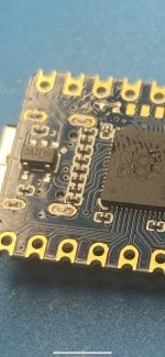
can anyone explain how to configure the led on the rp2040? do we need to solder some jumper on the chip?
Only if you get a green light immediately after programming. In this case, bridge the two pads like the pic.can anyone explain how to configure the led on the rp2040? do we need to solder some jumper on the chip?
Attachments
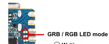
Exactly, when I program the chip, a green light appears and then goes off, does that mean something needs to be done with the rp2040?Only if you get a green light immediately after programming. In this case, bridge the two pads like the pic.
Set rgb modeExactly, when I program the chip, a green light appears and then goes off, does that mean something needs to be done with the rp2040?
View attachment 363777

https://github.com/Ansem-SoD/Picofly/tree/main/FirmwaresDoes someone have link or file to Picofly toolbox? Seems it has been removed
A (hopefully) final update to my first switch hacking saga. XD
I got my wireless function working again, and I managed to get rid of my slow emmc mode!
At some point during my hacking endeavors, I ripped the Dat0 trace and rendered my console unbootable...

While repairing that, I also ripped the CLK trace... So I scraped some of the solder mask away on the trace, then used uv-cure resin to mask off all the surrounding solder pads. I soldered to the tiniest pad that you can see above to the trace I exposed with 40awg magnet wire, then covered the whole thing in uv resin. I had to also repeat this process on the CLK trace.

Once I had finally gotten finished cleaning up my attempted failure of soldering to the emmc port pins (I shorted a bunch to ground since basically every other pin on the port is a GND pin -_-) I realized I had accidentally blown/brushed the tiny capacitors to the left of the APU shielding off, and these are ABSOLUTELY VITAL to the functioning of both wifi and bluetooth of the console. I repeat, if you rip these caps off, the joycons won't work unless docked in the switch, and you won't have wifi.
Here are the caps in question after I repaired them (I ALMOST ripped the trace of the one closest to the APU enough that I couldn't recover, but luckily I was able to offset the cap to hit the trace and the remaining pad on the circuit.)

And finally, if the above image doesn't QUITE give you the understanding of scale as to just how TINY these things are (literally smaller than a grain of rice) here is a photo of a single capacitor, resting on the pad of my thumb, a mere 2 finger-print traces long, perhaps 1 finger-print trace wide.

This was a real burning crucible experiment for me. Failing to fix this would mean I had a functioning switch, but no wifi and no wireless controllers could be used. I have an 8bitdo arcade stick that's compatible that would have been USELESS without this being fixed. I spent approximately FIVE HOURS positioning, cleaning, fluxing, tweezing, tweeking, nudging, holding my breath, swearing quietly, stabbing myself accidentally with pointy tweezers, and then finally getting a good connection on both capacitors to end with a RESOUNDING SUCCESS OF WORKING WIRELESS!
As far as my slow emmc problems go, I have a patched V1 and had 47O (47 ohm +/- 5%) on DAT0, CMD, and CLK, and hekate was reporting half-speed on my emmc. I replaced the 47O with 47RO (47 ohm +/- 1%) on CLK, and then put two 47RO in series on DAT0 and CMD to give them a total of 94 ohms resistance each. Doing this seems to have solved my slow emmc problems.
I'll be around, because I still have my GF's switch lite to hack, and potentially a few friend's switches. Keep hacking guys and gals, and if you think you've toasted your console, just consider how much I had to Frankenstein mine to keep it alive, and DON'T give up.
I got my wireless function working again, and I managed to get rid of my slow emmc mode!
At some point during my hacking endeavors, I ripped the Dat0 trace and rendered my console unbootable...
While repairing that, I also ripped the CLK trace... So I scraped some of the solder mask away on the trace, then used uv-cure resin to mask off all the surrounding solder pads. I soldered to the tiniest pad that you can see above to the trace I exposed with 40awg magnet wire, then covered the whole thing in uv resin. I had to also repeat this process on the CLK trace.
Once I had finally gotten finished cleaning up my attempted failure of soldering to the emmc port pins (I shorted a bunch to ground since basically every other pin on the port is a GND pin -_-) I realized I had accidentally blown/brushed the tiny capacitors to the left of the APU shielding off, and these are ABSOLUTELY VITAL to the functioning of both wifi and bluetooth of the console. I repeat, if you rip these caps off, the joycons won't work unless docked in the switch, and you won't have wifi.
Here are the caps in question after I repaired them (I ALMOST ripped the trace of the one closest to the APU enough that I couldn't recover, but luckily I was able to offset the cap to hit the trace and the remaining pad on the circuit.)
And finally, if the above image doesn't QUITE give you the understanding of scale as to just how TINY these things are (literally smaller than a grain of rice) here is a photo of a single capacitor, resting on the pad of my thumb, a mere 2 finger-print traces long, perhaps 1 finger-print trace wide.
This was a real burning crucible experiment for me. Failing to fix this would mean I had a functioning switch, but no wifi and no wireless controllers could be used. I have an 8bitdo arcade stick that's compatible that would have been USELESS without this being fixed. I spent approximately FIVE HOURS positioning, cleaning, fluxing, tweezing, tweeking, nudging, holding my breath, swearing quietly, stabbing myself accidentally with pointy tweezers, and then finally getting a good connection on both capacitors to end with a RESOUNDING SUCCESS OF WORKING WIRELESS!
As far as my slow emmc problems go, I have a patched V1 and had 47O (47 ohm +/- 5%) on DAT0, CMD, and CLK, and hekate was reporting half-speed on my emmc. I replaced the 47O with 47RO (47 ohm +/- 1%) on CLK, and then put two 47RO in series on DAT0 and CMD to give them a total of 94 ohms resistance each. Doing this seems to have solved my slow emmc problems.
I'll be around, because I still have my GF's switch lite to hack, and potentially a few friend's switches. Keep hacking guys and gals, and if you think you've toasted your console, just consider how much I had to Frankenstein mine to keep it alive, and DON'T give up.
Last edited by lightninjay,
Similar threads
- Replies
- 3
- Views
- 1K
- Replies
- 2
- Views
- 317
- Replies
- 42
- Views
- 6K
Site & Scene News
New Hot Discussed
-
-
23K views
Wii U and 3DS online services shutting down today, but Pretendo is here to save the day
Today, April 8th, 2024, at 4PM PT, marks the day in which Nintendo permanently ends support for both the 3DS and the Wii U online services, which include co-op play...by ShadowOne333 179 -
17K views
Nintendo Switch firmware update 18.0.1 has been released
A new Nintendo Switch firmware update is here. System software version 18.0.1 has been released. This update offers the typical stability features as all other... -
16K views
The first retro emulator hits Apple's App Store, but you should probably avoid it
With Apple having recently updated their guidelines for the App Store, iOS users have been left to speculate on specific wording and whether retro emulators as we... -
15K views
Delta emulator now available on the App Store for iOS
The time has finally come, and after many, many years (if not decades) of Apple users having to side load emulator apps into their iOS devices through unofficial...by ShadowOne333 96 -
15K views
MisterFPGA has been updated to include an official release for its Nintendo 64 core
The highly popular and accurate FPGA hardware, MisterFGPA, has received today a brand new update with a long-awaited feature, or rather, a new core for hardcore...by ShadowOne333 54 -
11K views
Nintendo takes down Gmod content from Steam's Workshop
Nintendo might just as well be a law firm more than a videogame company at this point in time, since they have yet again issued their now almost trademarked usual...by ShadowOne333 113 -
10K views
A prototype of the original "The Legend of Zelda" for NES has been found and preserved
Another video game prototype has been found and preserved, and this time, it's none other than the game that spawned an entire franchise beloved by many, the very...by ShadowOne333 31 -
9K views
TheFloW releases new PPPwn kernel exploit for PS4, works on firmware 11.00
TheFlow has done it again--a new kernel exploit has been released for PlayStation 4 consoles. This latest exploit is called PPPwn, and works on PlayStation 4 systems... -
9K views
Nintendo "Indie World" stream announced for April 17th, 2024
Nintendo has recently announced through their social media accounts that a new Indie World stream will be airing tomorrow, scheduled for April 17th, 2024 at 7 a.m. PT...by ShadowOne333 53 -
8K views
Anbernic reveals specs details of pocket-sized RG28XX retro handheld
Anbernic is back with yet another retro handheld device. The upcoming RG28XX is another console sporting the quad-core H700 chip of the company's recent RG35XX 2024...
-
-
-
179 replies
Wii U and 3DS online services shutting down today, but Pretendo is here to save the day
Today, April 8th, 2024, at 4PM PT, marks the day in which Nintendo permanently ends support for both the 3DS and the Wii U online services, which include co-op play...by ShadowOne333 -
113 replies
Nintendo takes down Gmod content from Steam's Workshop
Nintendo might just as well be a law firm more than a videogame company at this point in time, since they have yet again issued their now almost trademarked usual...by ShadowOne333 -
97 replies
The first retro emulator hits Apple's App Store, but you should probably avoid it
With Apple having recently updated their guidelines for the App Store, iOS users have been left to speculate on specific wording and whether retro emulators as we...by Scarlet -
96 replies
Delta emulator now available on the App Store for iOS
The time has finally come, and after many, many years (if not decades) of Apple users having to side load emulator apps into their iOS devices through unofficial...by ShadowOne333 -
79 replies
Nintendo Switch firmware update 18.0.1 has been released
A new Nintendo Switch firmware update is here. System software version 18.0.1 has been released. This update offers the typical stability features as all other...by Chary -
67 replies
TheFloW releases new PPPwn kernel exploit for PS4, works on firmware 11.00
TheFlow has done it again--a new kernel exploit has been released for PlayStation 4 consoles. This latest exploit is called PPPwn, and works on PlayStation 4 systems...by Chary -
55 replies
Nintendo Switch Online adds two more Nintendo 64 titles to its classic library
Two classic titles join the Nintendo Switch Online Expansion Pack game lineup. Available starting April 24th will be the motorcycle racing game Extreme G and another...by Chary -
54 replies
MisterFPGA has been updated to include an official release for its Nintendo 64 core
The highly popular and accurate FPGA hardware, MisterFGPA, has received today a brand new update with a long-awaited feature, or rather, a new core for hardcore...by ShadowOne333 -
53 replies
Nintendo "Indie World" stream announced for April 17th, 2024
Nintendo has recently announced through their social media accounts that a new Indie World stream will be airing tomorrow, scheduled for April 17th, 2024 at 7 a.m. PT...by ShadowOne333 -
52 replies
The FCC has voted to restore net neutrality, reversing ruling from 2017
In 2017, the United States Federal Communications Commission (FCC) repealed net neutrality. At the time, it was a major controversy between internet service providers...by Chary
-
Popular threads in this forum
General chit-chat
- No one is chatting at the moment.


