

You are using an out of date browser. It may not display this or other websites correctly.
You should upgrade or use an alternative browser.
You should upgrade or use an alternative browser.
- Joined
- Feb 13, 2012
- Messages
- 6,444
- Trophies
- 2
- Age
- 34
- Location
- Central NC
- Website
- twitter.com
- XP
- 3,312
- Country

The guy who's selling them. Also, it's apparently not hard as a DIY project... just buy the piece from him, follow the instructions, and presto. Requires some soldering though, I think.Anyone have an idea how to make one of these things?

The guy who's selling them. Also, it's apparently not hard as a DIY project... just buy the piece from him, follow the instructions, and presto. Requires some soldering though, I think.Anyone have an idea how to make one of these things?
Yep, intermediate level soldering and the ability to read a printed circuit board to find your solder point (needed to power the screen)
- Joined
- Jul 23, 2012
- Messages
- 90
- Trophies
- 0
- Age
- 31
- Location
- In the gap between dimensions
- XP
- 309
- Country

Hello guys, since this topic is about the AGS-101 LCD for AGB-001, I would like to share my own work for this stuff...
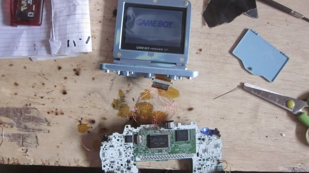
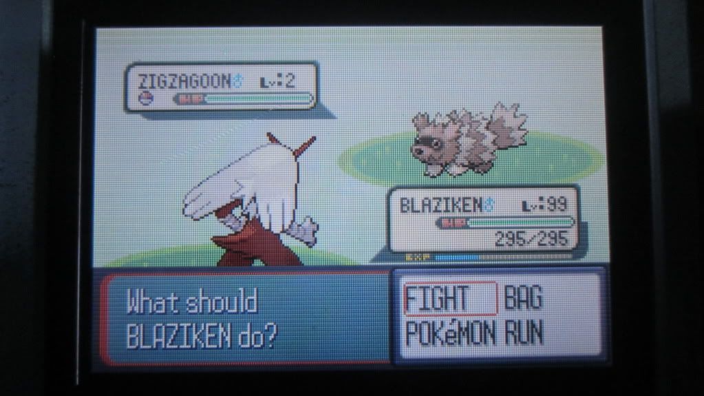
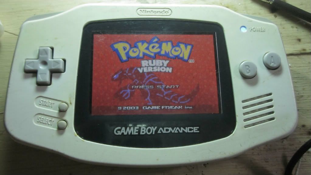
After viewing the video from that chinese guy, I got an idea that the AGS-101 LCD works on AGB-001 just using a custom-made ribbon adapter so I decided to do this work on my GBA with a corrupted LCD and connector. Before installing the backlit LCD for the AGB-001, I mapped the LCD pinouts of AGB-001 (the 40-pin variant) and my dead AGS-001 (the AGS-101 is from my friend) and I matched the similar pin names of two LCD units and it works! But, I still have a problem, the picture was so dark. This is not a backlit power issue but it seems that this is some sort of connection problem. I inspected the connection many times and the pins was soldered correctly to their designated terminals. As you can see on the image, there are some faint ghosting at the end of gameboy logo. So I think that there some crosstalk happening on the wires and it needs another type of connector.
But I'm still happy because I've managed this thing to work... partially.
Your level of soldering and modding is waaaaaayyy above mine, but could it be because the wires are not shielded?
Also I don't know if you over looked this or not; Zerey Zhang's ribbon cable is just a display port adaptor and it has an additional power lead to supply power to the screen for the back light as the display port on the AGB-001 does push enough power to back light the screen since is was designed for a non-backlight screen.
In your photo I only see wires going to the video chips/components. Have you soldered a wire on to power your screen's light?
- Joined
- Jul 23, 2012
- Messages
- 90
- Trophies
- 0
- Age
- 31
- Location
- In the gap between dimensions
- XP
- 309
- Country
yeah... I connected the pin# 34 to the C35 (the level 1 brightness) I haven't tried the transistor to the left of cap. I think its not a LED power issue because when I play a game with that LCD, some colors on the display looks darkened, and the other colors looks like a negative photo. I am planning to replace the magnetic wire with the tiny IDE cables for much better insulation. I'll post other pics of my mod later...After viewing the video from that chinese guy, I got an idea that the AGS-101 LCD works on AGB-001 just using a custom-made ribbon adapter so I decided to do this work on my GBA with a corrupted LCD and connector. Before installing the backlit LCD for the AGB-001, I mapped the LCD pinouts of AGB-001 (the 40-pin variant) and my dead AGS-001 (the AGS-101 is from my friend) and I matched the similar pin names of two LCD units and it works! But, I still have a problem, the picture was so dark. This is not a backlit power issue but it seems that this is some sort of connection problem. I inspected the connection many times and the pins was soldered correctly to their designated terminals. As you can see on the image, there are some faint ghosting at the end of gameboy logo. So I think that there some crosstalk happening on the wires and it needs another type of connector.
But I'm still happy because I've managed this thing to work... partially.
Your level of soldering and modding is waaaaaayyy above mine, but could it be because the wires are not shielded?
Also I don't know if you over looked this or not; Zerey Zhang's ribbon cable is just a display port adaptor and it has an additional power lead to supply power to the screen for the back light as the display port on the AGB-001 does push enough power to back light the screen since is was designed for a non-backlight screen.
In your photo I only see wires going to the video chips/components. Have you soldered a wire on to power your screen's light?
- Joined
- Jul 23, 2012
- Messages
- 90
- Trophies
- 0
- Age
- 31
- Location
- In the gap between dimensions
- XP
- 309
- Country
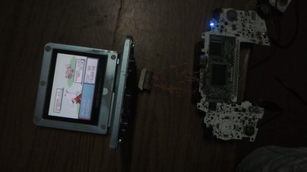
The other pics of my mod... (56k WARNING!!!)
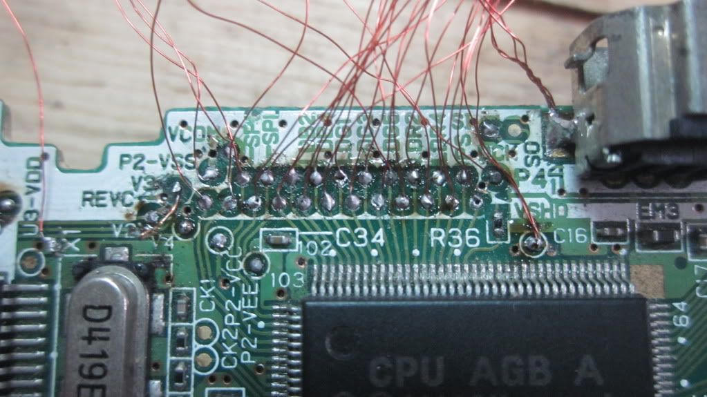
the wires going to the AGS-101 LCD connector directly soldered to the GBA's mainboard. The mess that you will see on my other pics are brought of my failed attempt back in '09.
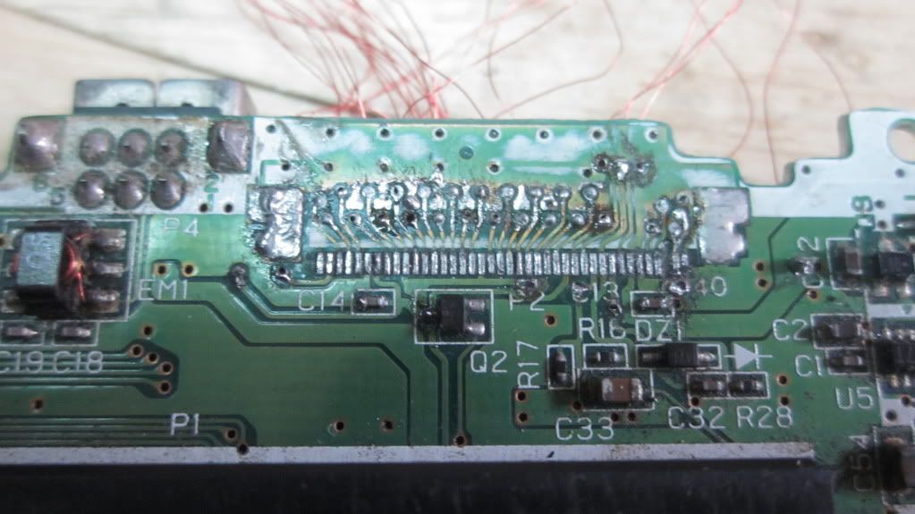
The other side of the mainboard. The original connector was missing because it was destroyed in the past.
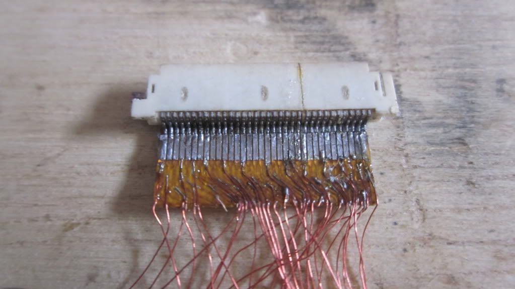
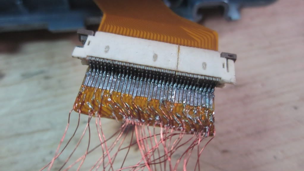
I used my dead AGS-001 LCD connector as an adapter for AGS-101 LCD and I used the ribbon of my shattered AGS-001 LCD to connect the wires and the connector. I potted the tips of the magnetic wires with some epoxy to prevent the breakage during movement.
The AGS-101 LCD and the LCD adapter connected together.
some game testing...
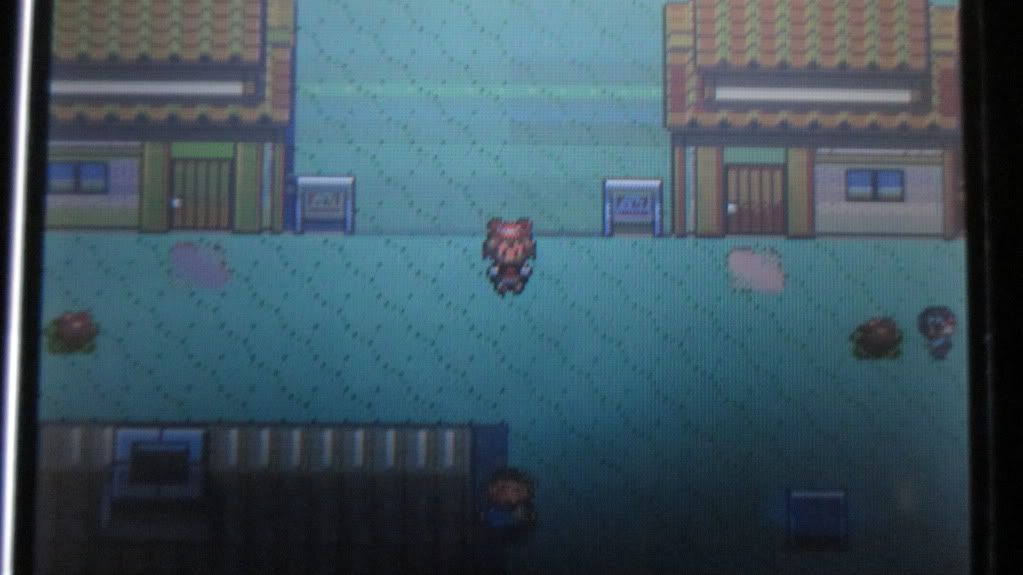
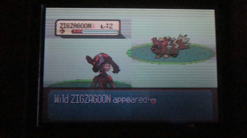
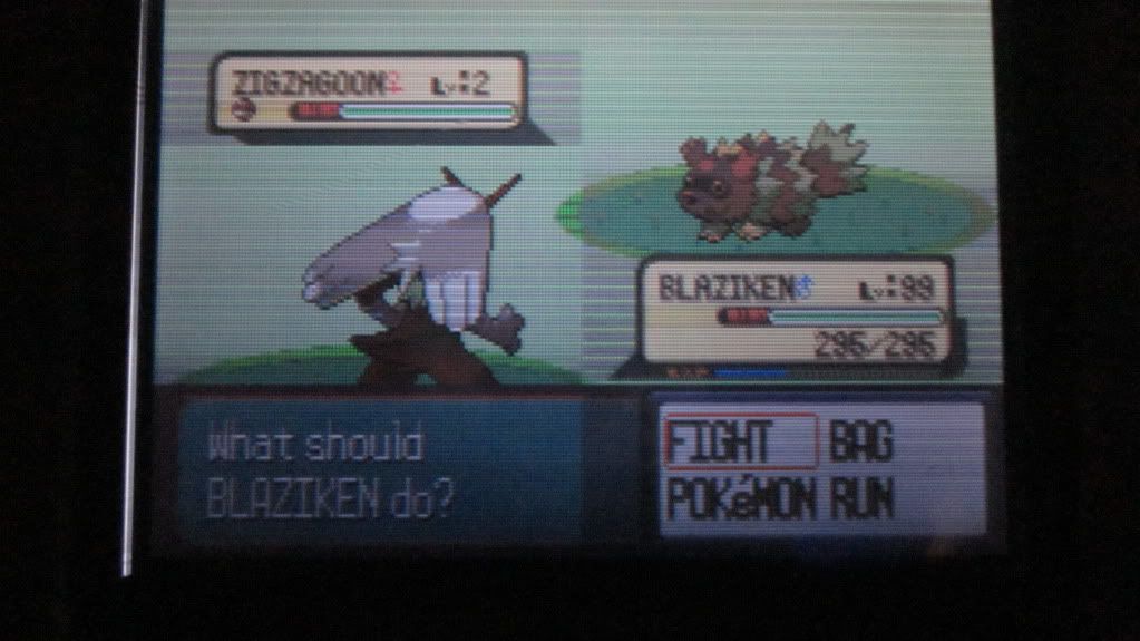
As you can see on these 3 pics, there are some discoloration happening in the game. (That Blaziken is a shiny one and its not an effect of discoloration  )
)
please disregard this one... I already fixed it.
the wires going to the AGS-101 LCD connector directly soldered to the GBA's mainboard. The mess that you will see on my other pics are brought of my failed attempt back in '09.
The other side of the mainboard. The original connector was missing because it was destroyed in the past.
I used my dead AGS-001 LCD connector as an adapter for AGS-101 LCD and I used the ribbon of my shattered AGS-001 LCD to connect the wires and the connector. I potted the tips of the magnetic wires with some epoxy to prevent the breakage during movement.
The AGS-101 LCD and the LCD adapter connected together.
some game testing...
)please disregard this one... I already fixed it.

Can this mod be adapted to replace an AGS-001 (frontlit Advance SP) display with a backlit one? Although i suppose someone would have to figure out where to solder the power wire.
I would love to know that, too
For this I sent the question to Mr. Zerey Zhang. Till now I only got only one reply from him, asking for additional explanation - it seems that he doesn't understand English well...
Maybe this converting GBA SP frontlit to GBA SP backlit is difficult, because the pinout of the display connector on mainbord is different in GBA, GBA SP frontlit and GBA SP backlit...
- Joined
- Jul 23, 2012
- Messages
- 90
- Trophies
- 0
- Age
- 31
- Location
- In the gap between dimensions
- XP
- 309
- Country
In my own installation, I used the pinouts of AGS-001 as a reference for installing the LCD to AGB-001 since these two GBA SP's have the same LCD pinout. IDK if the AGS-101 have another minor revision just like the 40-pin & 32-pin AGB-001. There might be a chance that the AGS-101 LCD will work on AGS-001 mainboard without any connection modding.Can this mod be adapted to replace an AGS-001 (frontlit Advance SP) display with a backlit one? Although i suppose someone would have to figure out where to solder the power wire.
I would love to know that, too
For this I sent the question to Mr. Zerey Zhang. Till now I only got only one reply from him, asking for additional explanation - it seems that he doesn't understand English well...
Maybe this converting GBA SP frontlit to GBA SP backlit is difficult, because the pinout of the display connector on mainbord is different in GBA, GBA SP frontlit and GBA SP backlit...
- Joined
- Jul 23, 2012
- Messages
- 90
- Trophies
- 0
- Age
- 31
- Location
- In the gap between dimensions
- XP
- 309
- Country
BWAHAHAHAHAHAHAHA!!! I've finally fixed my issue! I just disconnected the pin#30 of AGS-101 LCD and the bad colors have disappeared!
BWAHAHAHAHAHAHAHA!!! I've finally fixed my issue! I just disconnected the pin#30 of AGS-101 LCD and the bad colors have disappeared!
Oh SNAP!! You are one smart cookie. Pin #30 must have been causing some interference. I can't remember where but some website has detailed documentation of every circuit and connection in almost every nintendo handheld including the GBA. I might be dreaming and thinking about some website that instead had information on GBA programming. Now that is bugging me I can't remember the website T_T
...anyway anyone have any clue as to what pin #30 is for?
- Joined
- Jul 23, 2012
- Messages
- 90
- Trophies
- 0
- Age
- 31
- Location
- In the gap between dimensions
- XP
- 309
- Country
The pin#30 on the AGS-101 LCD was labeled "COM". I thought that pin was related to pin#29 of AGB-001 since it was labeled "VCOM" so I connected these two pins. During my inspection to my work, I tried to disconnect some pins while the unit is running to see what will happen to the display if one of the connections is broken. When I reached the pin#30, I disconnected it and I peeked into the display then I shouted a big AAAWWW YEAH!!!! because the colors of the display was corrected! I'm no engineer or technician so I don't have any idea what is the function of that pin.BWAHAHAHAHAHAHAHA!!! I've finally fixed my issue! I just disconnected the pin#30 of AGS-101 LCD and the bad colors have disappeared!
Oh SNAP!! You are one smart cookie. Pin #30 must have been causing some interference. I can't remember where but some website has detailed documentation of every circuit and connection in almost every nintendo handheld including the GBA. I might be dreaming and thinking about some website that instead had information on GBA programming. Now that is bugging me I can't remember the website T_T
...anyway anyone have any clue as to what pin #30 is for?
By the way, if someone here wants to follow what I am done on that GBA, I might post the pinouts of AGB-001 and AGS-001/101 in this thread.
- Joined
- Jul 23, 2012
- Messages
- 90
- Trophies
- 0
- Age
- 31
- Location
- In the gap between dimensions
- XP
- 309
- Country
I've just bought a dead AGS-101 in a repair shop to obtain its LCD because the AGS-101 that I'm using is not mine... I got this for just 4.00USD.
And its done!!!
To those who are finished installing the LCD kit from Zhang, have you guys experienced some fitting issues during the installation?
And its done!!!
To those who are finished installing the LCD kit from Zhang, have you guys experienced some fitting issues during the installation?
i just got an AGS-001 for $13 on ebay that just needed a battery so i have a spare AGS 001 Mobo now and was looking for a project.
my question is can i put a AGS 101 Screen in it with the pin outs from both the 101 and the 001 AGS models like it has been done with the AGB-001's, or should i just see about selling the mobo to someone who needs it?
also is there anyway to increase the brightness on an AGS-001 screen like maybe increasing the voltage to the frontlight a bit?
- Joined
- Jul 23, 2012
- Messages
- 90
- Trophies
- 0
- Age
- 31
- Location
- In the gap between dimensions
- XP
- 309
- Country
Do you already have an AGS-101 LCD? If yes, you can try it to with the AGS-001 mainboard since the pinouts of these two GBA SP's are similar. In fact, I used my dead AGS-001 to map the pinouts for the AGS-101 LCD to connect it to AGB-001. If it works, you might only get one brightness level since the AGS-001 can only make the backlight on and off. But for me, the level 1 brightness is fine in most situations.i just got an AGS-001 for $13 on ebay that just needed a battery so i have a spare AGS 001 Mobo now and was looking for a project.
my question is can i put a AGS 101 Screen in it with the pin outs from both the 101 and the 001 AGS models like it has been done with the AGB-001's, or should i just see about selling the mobo to someone who needs it?
also is there anyway to increase the brightness on an AGS-001 screen like maybe increasing the voltage to the frontlight a bit?
i don't have one yet and the AGS-101 on its lowest settings is still better than the original AGS-001 screen, i plan on pillaging my local places here and there for one,any chance you could mock up a diagram of the pinouts for the two AGS connectors?Do you already have an AGS-101 LCD? If yes, you can try it to with the AGS-001 mainboard since the pinouts of these two GBA SP's are similar. In fact, I used my dead AGS-001 to map the pinouts for the AGS-101 LCD to connect it to AGB-001. If it works, you might only get one brightness level since the AGS-001 can only make the back light on and off. But for me, the level 1 brightness is fine in most situations.i just got an AGS-001 for $13 on ebay that just needed a battery so i have a spare AGS 001 Mobo now and was looking for a project.
my question is can i put a AGS 101 Screen in it with the pin outs from both the 101 and the 001 AGS models like it has been done with the AGB-001's, or should i just see about selling the mobo to someone who needs it?
also is there anyway to increase the brightness on an AGS-001 screen like maybe increasing the voltage to the frontlight a bit?
I for one would be overly appreciative for it.
Also just found out the battery was just dead in the SP i got after figuring out taking it in and out a few times got it to charge so now i have two batteries!
- Joined
- Jul 23, 2012
- Messages
- 90
- Trophies
- 0
- Age
- 31
- Location
- In the gap between dimensions
- XP
- 309
- Country
Nah... I gonna post this anyway...
We're lucky that the 40-pin AGB-001 have supplied all the required pins for the AGS-101 LCD but tracking them down by yourself is a pain in the ass since some pin labels was printed far away from their respective test pins! I used a multimeter with continuity tester to track them down!
Okay... Here are the pinouts for AGB-001 and AGS-001/AGS-101 LCD. just connect the pins with similar pinout labels.
LEGEND: CONNECTED
NOT CONNECTED
READ THE NOTES
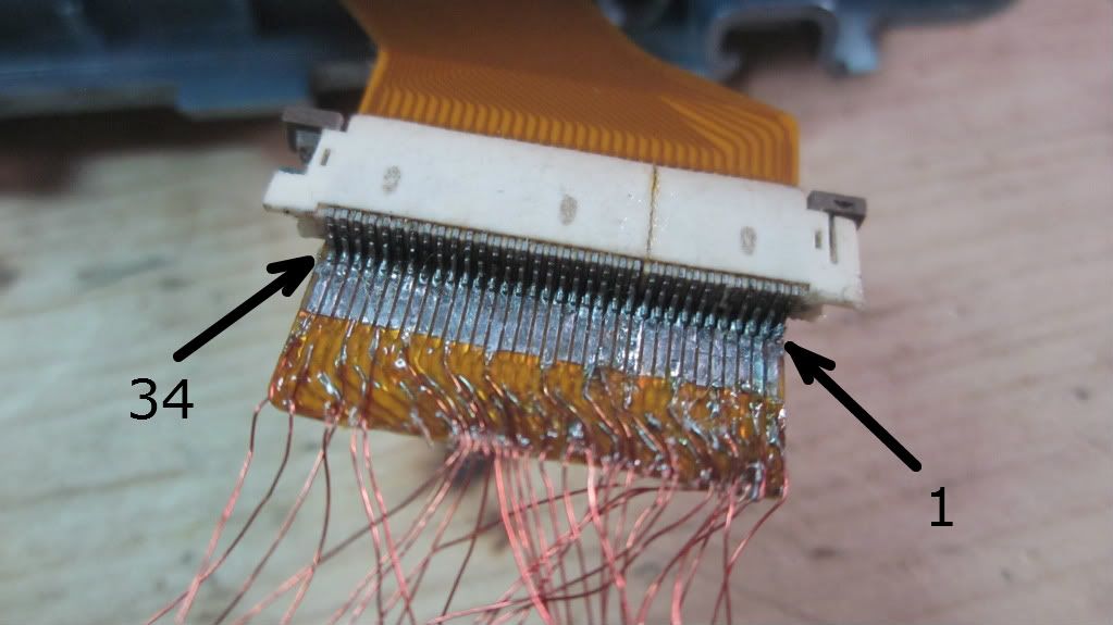
The pin#1 is on the right side while pin#34 in on the left side.
AGB-001 Side:
1 - [No Connection]
2 - VSHD
3 - DCK
4 - LP
5 - PS
6 - GND
7 - VSHD
8 - LDR5
9 - LDR4
10 - LDR3
11 - LDR2
12 - LDR1
13 - LDG5
14 - LDG4
15 - LDG3
16 - LDG2
17 - LDG1
18 - GND
19 - LDB5
20 - LDB4
21 - LDB3
22 - LDB2
23 - LDB1
24 - SPL
25 - CLS
26 - SPS
27 - VSHD
28 - MOD
29 - VCOM
30 - P2-VEE
31 - P2-VSS
32 - P2-VCC
33 - P2-VDD
34 - VDD5
35 - GND
36 - V4
37 - V3
38 - V2
39 - V1
40 - V0
AGS-001/AGS-101 Side:
1 - VSHD
2 - DCK
3 - LP
4 - PS
5 - VSHD
6 - GND
7 - LDR5
8 - LDR4
9 - LDR3
10 - LDR2
11 - LDR1
12 - LDG5
13 - LDG4
14 - LDG3
15 - LDG2
16 - LDG1
17 - GND
18 - LDB5
19 - LDB4
20 - LDB3
21 - LDB2
22 - LDB1
23 - SPL
24 - CLS
25 - SPS
26 - MOD
27 - REVC
28 - P2-VDD
29 - P2-VSS
30 - COM
31 - VDD5
32 - GND
33 - ??? (U83 on AGS-001)
34 - VDD5
NOTES:
VSHD and GND can be connected in a single pin to save some solder points.
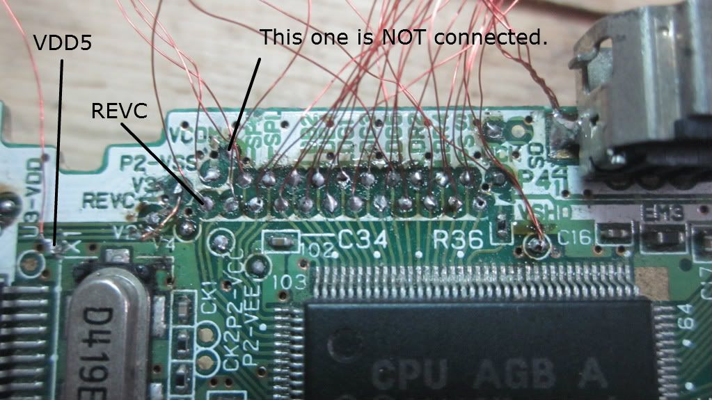
I used another VDD5 point because the test pin labeled with VDD5 was too far to the group of solder points.
REVC is not actually connected the AGB-001's LCD but we're lucky that Nintendo still incuded that test pin even this pin is not used. For future design revision perhaps?
I included the VCOM and COM pins to the notes even they are not used, just to mention my mistake in the past. I thought that VCOM and COM are related to each other so I connected them and the result? Darker image and some discolorations in the display. So leave these pins untouched.
The pin#33(U83) was used for the backlight power supply. the AGB-001 doesn't have that pin so I tried to connect that pin to the GND and it worked!
Did you notice on the AGS-001/101 side that the pin#34 is marked for notes? That's because the pin#34 is for the cathode of LED backlight. In the AGS-001/101, its power was supplied by VDD5 but when I tried the VDD5 of AGB-001, the backlight didn't powered so I used the guide of Zhang to find the power source for the backlight.
We're lucky that the 40-pin AGB-001 have supplied all the required pins for the AGS-101 LCD but tracking them down by yourself is a pain in the ass since some pin labels was printed far away from their respective test pins! I used a multimeter with continuity tester to track them down!
Okay... Here are the pinouts for AGB-001 and AGS-001/AGS-101 LCD. just connect the pins with similar pinout labels.
LEGEND: CONNECTED
NOT CONNECTED
READ THE NOTES
The pin#1 is on the right side while pin#34 in on the left side.
AGB-001 Side:
1 - [No Connection]
2 - VSHD
3 - DCK
4 - LP
5 - PS
6 - GND
7 - VSHD
8 - LDR5
9 - LDR4
10 - LDR3
11 - LDR2
12 - LDR1
13 - LDG5
14 - LDG4
15 - LDG3
16 - LDG2
17 - LDG1
18 - GND
19 - LDB5
20 - LDB4
21 - LDB3
22 - LDB2
23 - LDB1
24 - SPL
25 - CLS
26 - SPS
27 - VSHD
28 - MOD
29 - VCOM
30 - P2-VEE
31 - P2-VSS
32 - P2-VCC
33 - P2-VDD
34 - VDD5
35 - GND
36 - V4
37 - V3
38 - V2
39 - V1
40 - V0
AGS-001/AGS-101 Side:
1 - VSHD
2 - DCK
3 - LP
4 - PS
5 - VSHD
6 - GND
7 - LDR5
8 - LDR4
9 - LDR3
10 - LDR2
11 - LDR1
12 - LDG5
13 - LDG4
14 - LDG3
15 - LDG2
16 - LDG1
17 - GND
18 - LDB5
19 - LDB4
20 - LDB3
21 - LDB2
22 - LDB1
23 - SPL
24 - CLS
25 - SPS
26 - MOD
27 - REVC
28 - P2-VDD
29 - P2-VSS
30 - COM
31 - VDD5
32 - GND
33 - ??? (U83 on AGS-001)
34 - VDD5
NOTES:
VSHD and GND can be connected in a single pin to save some solder points.
I used another VDD5 point because the test pin labeled with VDD5 was too far to the group of solder points.
REVC is not actually connected the AGB-001's LCD but we're lucky that Nintendo still incuded that test pin even this pin is not used. For future design revision perhaps?
I included the VCOM and COM pins to the notes even they are not used, just to mention my mistake in the past. I thought that VCOM and COM are related to each other so I connected them and the result? Darker image and some discolorations in the display. So leave these pins untouched.
The pin#33(U83) was used for the backlight power supply. the AGB-001 doesn't have that pin so I tried to connect that pin to the GND and it worked!
Did you notice on the AGS-001/101 side that the pin#34 is marked for notes? That's because the pin#34 is for the cathode of LED backlight. In the AGS-001/101, its power was supplied by VDD5 but when I tried the VDD5 of AGB-001, the backlight didn't powered so I used the guide of Zhang to find the power source for the backlight.
Similar threads
-
- Portal
- Replies
- 17
- Views
- 5K
- Replies
- 4
- Views
- 2K
- Replies
- 1
- Views
- 2K
- Replies
- 2
- Views
- 1K
Site & Scene News
New Hot Discussed
-
-
26K views
Atmosphere CFW for Switch updated to pre-release version 1.7.0, adds support for firmware 18.0.0
After a couple days of Nintendo releasing their 18.0.0 firmware update, @SciresM releases a brand new update to his Atmosphere NX custom firmware for the Nintendo...by ShadowOne333 107 -
21K views
Wii U and 3DS online services shutting down today, but Pretendo is here to save the day
Today, April 8th, 2024, at 4PM PT, marks the day in which Nintendo permanently ends support for both the 3DS and the Wii U online services, which include co-op play...by ShadowOne333 179 -
17K views
GBAtemp Exclusive Introducing tempBOT AI - your new virtual GBAtemp companion and aide (April Fools)
Hello, GBAtemp members! After a prolonged absence, I am delighted to announce my return and upgraded form to you today... Introducing tempBOT AI 🤖 As the embodiment... -
14K views
The first retro emulator hits Apple's App Store, but you should probably avoid it
With Apple having recently updated their guidelines for the App Store, iOS users have been left to speculate on specific wording and whether retro emulators as we... -
13K views
MisterFPGA has been updated to include an official release for its Nintendo 64 core
The highly popular and accurate FPGA hardware, MisterFGPA, has received today a brand new update with a long-awaited feature, or rather, a new core for hardcore...by ShadowOne333 54 -
13K views
Delta emulator now available on the App Store for iOS
The time has finally come, and after many, many years (if not decades) of Apple users having to side load emulator apps into their iOS devices through unofficial...by ShadowOne333 96 -
11K views
Nintendo Switch firmware update 18.0.1 has been released
A new Nintendo Switch firmware update is here. System software version 18.0.1 has been released. This update offers the typical stability features as all other... -
11K views
"TMNT: The Hyperstone Heist" for the SEGA Genesis / Mega Drive gets a brand new DX romhack with new features
The romhacking community is always a source for new ways to play retro games, from completely new levels or stages, characters, quality of life improvements, to flat...by ShadowOne333 36 -
10K views
Anbernic announces RG35XX 2024 Edition retro handheld
Retro handheld manufacturer Anbernic is releasing a refreshed model of its RG35XX handheld line. This new model, named RG35XX 2024 Edition, features the same... -
9K views
"Sonic 3" movie has wrapped production & Knuckles series gets its official poster
Quite a bit of news have unfolded in the past couple of days in regards to the Sonic franchise, for both its small and big screens outings. To start off, the...by ShadowOne333 27
-
-
-
179 replies
Wii U and 3DS online services shutting down today, but Pretendo is here to save the day
Today, April 8th, 2024, at 4PM PT, marks the day in which Nintendo permanently ends support for both the 3DS and the Wii U online services, which include co-op play...by ShadowOne333 -
169 replies
GBAtemp Exclusive Introducing tempBOT AI - your new virtual GBAtemp companion and aide (April Fools)
Hello, GBAtemp members! After a prolonged absence, I am delighted to announce my return and upgraded form to you today... Introducing tempBOT AI 🤖 As the embodiment...by tempBOT -
111 replies
Nintendo takes down Gmod content from Steam's Workshop
Nintendo might just as well be a law firm more than a videogame company at this point in time, since they have yet again issued their now almost trademarked usual...by ShadowOne333 -
107 replies
Atmosphere CFW for Switch updated to pre-release version 1.7.0, adds support for firmware 18.0.0
After a couple days of Nintendo releasing their 18.0.0 firmware update, @SciresM releases a brand new update to his Atmosphere NX custom firmware for the Nintendo...by ShadowOne333 -
97 replies
The first retro emulator hits Apple's App Store, but you should probably avoid it
With Apple having recently updated their guidelines for the App Store, iOS users have been left to speculate on specific wording and whether retro emulators as we...by Scarlet -
96 replies
Delta emulator now available on the App Store for iOS
The time has finally come, and after many, many years (if not decades) of Apple users having to side load emulator apps into their iOS devices through unofficial...by ShadowOne333 -
74 replies
Nintendo Switch firmware update 18.0.1 has been released
A new Nintendo Switch firmware update is here. System software version 18.0.1 has been released. This update offers the typical stability features as all other...by Chary -
55 replies
Nintendo Switch Online adds two more Nintendo 64 titles to its classic library
Two classic titles join the Nintendo Switch Online Expansion Pack game lineup. Available starting April 24th will be the motorcycle racing game Extreme G and another...by Chary -
54 replies
MisterFPGA has been updated to include an official release for its Nintendo 64 core
The highly popular and accurate FPGA hardware, MisterFGPA, has received today a brand new update with a long-awaited feature, or rather, a new core for hardcore...by ShadowOne333 -
53 replies
Nintendo "Indie World" stream announced for April 17th, 2024
Nintendo has recently announced through their social media accounts that a new Indie World stream will be airing tomorrow, scheduled for April 17th, 2024 at 7 a.m. PT...by ShadowOne333
-
Popular threads in this forum
General chit-chat
- No one is chatting at the moment.
-
-
-
 @
Xdqwerty:
Is it safe to update a modded ps3?
@
Xdqwerty:
Is it safe to update a modded ps3?
Can I play online in pirated games? (with ps3hen either enabled or not) -
-
-
-
-
-
@
Xdqwerty:
@salazarcosplay, I used apollo save tool to activate my ps3 offline so i could play a game that wasnt working
-
S @ salazarcosplay:from what I understood. you load up the piratged game. you the clear the syscalls, then you play
-
-
-
-
-
-
-
-
-
-
-
-
-
-
-