Hi ServenIkhana.
Yes, there are about 13.5V on the D1A pin, but after connecting the LCD backlight the voltage drops to 11V, because it cannot supply enough current. LEDs are non-linear devices, so altought it could be hard to believe, there is a big diference in brightness and current between 11V and 12V. Unfortunately, there is no point inside the gba with 12V, capable of supplying enough current for getting the LCD maximum bright level. And that's why external circuitry is needed.
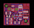
Referring P1, I can't tell if it is mandatory to isolate it (using my 12V step up regulator I can assure is mandatory to isolate), because as soon as I received my adapter I cut the trace (just to be safe). But there are people complaining about the console turning off after soldering the cable, so I asume this could be the reason. Anyway, I highly recommend you to isolate it, to avoid shorting the 5V rail with the 13.5V one. In the 32 pin adapter I have is very easy to do, I attach a photo showing where to cut (don't know if yours is different).
After cutting that trace, the backlight will no longer be powered trough the 5V rail (it will stop working), so you can connect it to wherever you want (3.3V, 5V, D1A...).
Ok, thanks.
I have the same adapter so for avoid problems initially I will cut that trace and solder P1 to D1A. If the brightness isn't enough for me I will try your solution, but is unlikely since I'm used to use screens with not much brightness.
Have you considered selling these PCBs or sharing the schematics?
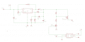
The input for the step-up converter is the 3.3v regulated rail or the raw batteries?