Hardware GBA Backlight! (AGB-001)

Rosni

Member
Newcomer
Joined
Jul 31, 2015
Messages
9
Trophies
0
XP
101
Country
Spain
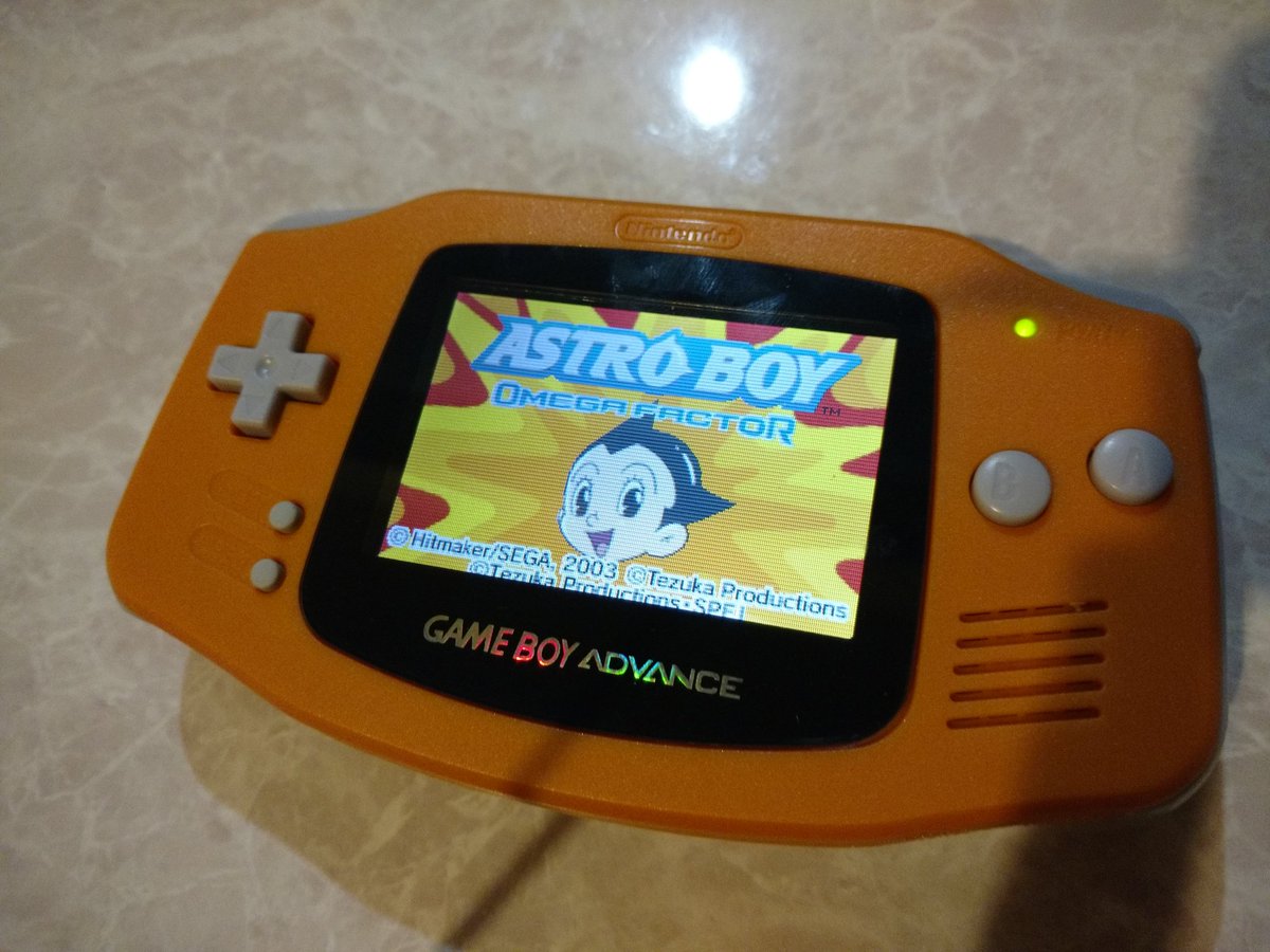
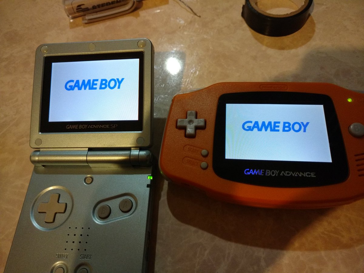
Please guys, can you share all variations for solder points on 40 pins GBA's?Those motherboards are a disaster. I've backlighted 3 GBA's with aliexpress ribbon, first of them I solved with P2-VEE(near 103) to GROUND.
I tried same on the next two, but LCD's showed two differents tones on it. So, I returned to investigate and I found REVC to GROUND solution, this works with one GBA not perfect solution, minor ghosting on some games but colurs look amazing.
In the last GBA using REVC to GROUND colours are too darkest and a lot of image retention appears, so I don't know what will be the next attempt, any advice?

P.S: White tabs LCD's on three GBA's.
P.S2: Sorry my english. I hope you understand me.

EDIT: I've found this ribbon on aliexpress:

https://www.aliexpress.com/item/32P...1-Backlit-Adapter-Screen-Mod/32716977370.html

It reminds me leechan ribbon adaptors(the good ones). Problem is seller doesn't know what is difference(between A and B model) and what ribbon is necessary for LCD he sells(white tab), I'm thinking is B model for white tabs, but I need his confirmation, and no emojis as answer. It's frustating talking with some sellers.
 
Last edited by Rosni,

bossmustang429

New Member
Newbie
Joined
Sep 15, 2016
Messages
2
Trophies
0
Age
28
XP
52
Country
United States

Attachments

  • IMG_20160910_082833.jpg
    IMG_20160910_082833.jpg
    228.2 KB · Views: 477
Last edited by bossmustang429,

Rosni

Member
Newcomer
Joined
Jul 31, 2015
Messages
9
Trophies
0
XP
101
Country
Spain

bossmustang429

New Member
Newbie
Joined
Sep 15, 2016
Messages
2
Trophies
0
Age
28
XP
52
Country
United States

Rosni

Member
Newcomer
Joined
Jul 31, 2015
Messages
9
Trophies
0
XP
101
Country
Spain
When I solder the p1 on the ribbon cable to the point the PDF shows the gba turns on and instantly back off I've made sure it's not shorting any of the other points near it remove the wire fix the problem allowing the gba to turn back on

I don't know what is happening, 32 pin motherboards usually work very good. I've solder this two points (p1 to transistor) in various consoles and I never had any problem.
 

marcos862

Member
Newcomer
Joined
Sep 26, 2016
Messages
10
Trophies
0
Age
38
XP
55
Country
Mexico
I am trying to see if someone could help me on here, I was trying to do a backlight mod on a GBA but I've ran into a problem. The screen I pulled from a AGS-101 which is a brown tab type AB is not powering on the screen when I turn on my GBA. I have a 40 pin GBA ive tried to solder the P1 to DA1 without any success. Please let me know if there is other ways around this problem, thanks.

Hey I'm having a problem with my brightness being to dim it's an ags-101 screen on a 32 pin and I can't seem to figure it out I got the cable from http://handheldlegend.com/collections/gba-products/products/gameboy-advance-ags-ribbon-cable-adapter

I'm having a similar issue here, what i have is a 40pin mainboard with a brown tab type AB LCD screen. What i'm getting is a very dim image as the one show by @bossmustang429.

I'm not sure if @Enemysquad is getting a similar issue or the whole LCD screen doesn't turn on.

I have also solder the P1 to DA1 without any difference, i have read that some users have solve this same issue changing the LCD Screen. I have another LCD screen, same AB type, and the result was the same, very dim image.

Any idea, suggestion?
 

marcos862

Member
Newcomer
Joined
Sep 26, 2016
Messages
10
Trophies
0
Age
38
XP
55
Country
Mexico
Good Day!!

I finally solve my problem, partially, let me explain.

Basically, the 40pin ribbon cable adapter that i got, looks like it was defective so, the seller send me a 32pin ribbon cable adapter and a mainboard.

When i connect the cable and solder the cable from P1 (ribbon cable) to the left leg of the DA1 i tested the mod and the gba doesn't turn on, so, i disconnect everything and start checking the ribbon cable and i have found that, where the C2 label is located, the cable was manufacture with a short circuit there, so, i think that the objective of this is to "avoid" the solder part, but, without soldering the cable, the screen was very dimm, so, what i did was, with a cutter, i remove the short circuit in C2 and when i tested again (with the cable solder from P1 to DA1) the screen works correctly!!

By the way, i was still using the same LCD screen AB type. So, i can confirm that an AB LCD Screen type can works without issue with a 32pins GBA.

CuDqshuUEAAmpjK.jpg


GBA AGS 101 vs GBA mod
CuDquH0VMAAOklf.jpg


- Marcos I.
 

Le_Gogh

Member
Newcomer
Joined
Oct 19, 2016
Messages
21
Trophies
0
Age
37
XP
65
Country
Hi guys, been lurking here over the last few months while I got everything I need together for my backlight mod. I've read through this entire thread, and various others, and am having an issue with the mod. Thought it might help to sign up and ask for some help!

I currently have a 32 pin board, and a white tabbed screen, with the correct 32 pin adapter. After soldering the two points today all I'm getting is a blank white screen, with sound (i.e. the game is playing but you just can't see anything at all). Adjusting the pot makes no difference, and I've fiddled with the various suggestions previously mentioned but with no luck. Do you think it could be a faulty ribbon adapter?

Happy to provide images if needed.
 

marcos862

Member
Newcomer
Joined
Sep 26, 2016
Messages
10
Trophies
0
Age
38
XP
55
Country
Mexico
Hi guys, been lurking here over the last few months while I got everything I need together for my backlight mod. I've read through this entire thread, and various others, and am having an issue with the mod. Thought it might help to sign up and ask for some help!

I currently have a 32 pin board, and a white tabbed screen, with the correct 32 pin adapter. After soldering the two points today all I'm getting is a blank white screen, with sound (i.e. the game is playing but you just can't see anything at all). Adjusting the pot makes no difference, and I've fiddled with the various suggestions previously mentioned but with no luck. Do you think it could be a faulty ribbon adapter?

Happy to provide images if needed.

According to what you are describing... looks like that the cable is not well connected, you should check both sides of the ribbon cable, the one that goes to the screen and the other that goes to the mainboard.

I have seen two different behaviors with this ribbon cables, in some mainboards they are very tight and you need to push a little harder to make it make a good connections, in the other hand, i have seen that there are some mainboards where the cable connects very easy and sometimes, i had problems because the cable was "too inside" of the connector, so, you need to pull it a little out.

By the way... did you test the screen before??
 

Le_Gogh

Member
Newcomer
Joined
Oct 19, 2016
Messages
21
Trophies
0
Age
37
XP
65
Country
The ordinary non-backlit screen still works fine, but I have no way of actually testing the new screen itself. I've soldered c35 to P1 for the higher brightness setting to see if that changes anything and it's no different.

I've rechecked the ribbon cable connections and its physically impossible for me to insert them any further, so they must be in right? I guess I should contact the seller of the adapter and see if they can send me a new one, I feel as though it must be the ribbon cable...

Edit: Can't seem to attach an image - here: http://s56.photobucket.com/user/Newarky/media/Mobile Uploads/IMG_20161019_182120.jpg.html

I also tested some wiring on the GND, REVC and COM points on the front but that just made the light duller, and there was still no image at all.
 
Last edited by Le_Gogh,

marcos862

Member
Newcomer
Joined
Sep 26, 2016
Messages
10
Trophies
0
Age
38
XP
55
Country
Mexico
The ordinary non-backlit screen still works fine, but I have no way of actually testing the new screen itself. I've soldered c35 to P1 for the higher brightness setting to see if that changes anything and it's no different.

I've rechecked the ribbon cable connections and its physically impossible for me to insert them any further, so they must be in right? I guess I should contact the seller of the adapter and see if they can send me a new one, I feel as though it must be the ribbon cable...

Edit: Can't seem to attach an image - here: http://s56.photobucket.com/user/Newarky/media/Mobile Uploads/IMG_20161019_182120.jpg.html

I also tested some wiring on the GND, REVC and COM points on the front but that just made the light duller, and there was still no image at all.

I can't see in your pictures but... maybe you are having a similar problem than me... did you try disconnecting the P1 to C35 cable and see what happen?

Also, can you post a picture of your ribbon cable of the other side? where is the P1, P2, C1 and C2 labels, i just want to check something.

Thanks!
 

marcos862

Member
Newcomer
Joined
Sep 26, 2016
Messages
10
Trophies
0
Age
38
XP
55
Country
Mexico
Of course, here you go:

http://i56.photobucket.com/albums/g174/Newarky/Mobile Uploads/IMG_20161019_195829.jpg

Edit: this photo may be better http://i56.photobucket.com/albums/g174/Newarky/Mobile Uploads/IMG_20161019_195810.jpg

If I disconnect the cable the screen is completely black, nothing at all.

Any advice? I appreciate the help!

Ok... i have seen your pictures and... looks like that the cable is not well connected, because if you see, there is some copper showing after you connect the cable, also, if you take a look in the P1 and follow the trace, the C2 is doing a short circuit between two pins, the last one and the previous to the last one.

These both things make me thing that the cable is not well connected. If you don't cut the C2 connection, when you connect correctly the ribbon cable to the mainboard you will see the same behavior as the one that i was having, when you turn on the gba it will not be able to turn on because the short circuit between the C2 and P1.

I was also having the same issue, it was a very difficult to connect the ribbon cable correctly with the mainboard, because it's very tight, looks like that the ribbon cable is a thicker than the original cable. One recommendation is to try to introduce the ribbon cable with some angle, that helps me, basically, almost all the copper should be inside the connector.
 

Le_Gogh

Member
Newcomer
Joined
Oct 19, 2016
Messages
21
Trophies
0
Age
37
XP
65
Country
Ok... i have seen your pictures and... looks like that the cable is not well connected, because if you see, there is some copper showing after you connect the cable, also, if you take a look in the P1 and follow the trace, the C2 is doing a short circuit between two pins, the last one and the previous to the last one.

These both things make me thing that the cable is not well connected. If you don't cut the C2 connection, when you connect correctly the ribbon cable to the mainboard you will see the same behavior as the one that i was having, when you turn on the gba it will not be able to turn on because the short circuit between the C2 and P1.

I was also having the same issue, it was a very difficult to connect the ribbon cable correctly with the mainboard, because it's very tight, looks like that the ribbon cable is a thicker than the original cable. One recommendation is to try to introduce the ribbon cable with some angle, that helps me, basically, almost all the copper should be inside the connector.

OK thanks, I will try and move the ribbon cable and see whether it is simply the connection to the board.

In terms of cutting the ribbon cable itself, I assume you mean here? http://i56.photobucket.com/albums/g174/Newarky/Mobile Uploads/IMG_20161019_195810_01_01.jpg
 
Last edited by Le_Gogh,

Le_Gogh

Member
Newcomer
Joined
Oct 19, 2016
Messages
21
Trophies
0
Age
37
XP
65
Country
Yes, exactly there.

Well I cut it, and it made no difference unfortunately.

That said, a second screen arrived today and it has exactly the same issue. This therefore makes me feel it's either a defective board, or the ribbon adapter is faulty. I've ordered a new ribbon, and will see if that makes a difference, if not I guess I'm on the hunt for another 32 pin board...

Thanks for your help. Will post back when the new cable arrives.
 

Testo90

Well-Known Member
Member
Joined
Mar 14, 2015
Messages
160
Trophies
0
Age
44
Location
Badung, Bali, Indonesia
XP
363
Country
Gambia, The
Well I cut it, and it made no difference unfortunately.

That said, a second screen arrived today and it has exactly the same issue. This therefore makes me feel it's either a defective board, or the ribbon adapter is faulty. I've ordered a new ribbon, and will see if that makes a difference, if not I guess I'm on the hunt for another 32 pin board...

Thanks for your help. Will post back when the new cable arrives.
Got the Same Problem... it worked with a New Ribbon Cable
 

Le_Gogh

Member
Newcomer
Joined
Oct 19, 2016
Messages
21
Trophies
0
Age
37
XP
65
Country
Got the Same Problem... it worked with a New Ribbon Cable

Thanks! That's good to know!

I've sourced a new GBA as well. Figured if it's the cable then at least I can make two and sell one or gift it to a friend for Christmas or something.

Mind me asking which cable you used?
 

Kevin29

Member
Newcomer
Joined
Oct 22, 2016
Messages
10
Trophies
0
Age
34
XP
53
Country
Netherlands
Hi all,
I got a 32 pin and 40 pin GBA. I also got a GBA SP 101 with the white connector with uniform widths. I saw that I best could use the 32 pin GBA to do this mod. But will my screen of the AGS 101 work good on the GBA? I saw on https://gist.github.com/grantland/8c112548b44aa87dced2 that the A type will work the best with a 32pin GBA. But there are AB, A and B screens, right? So the problem is that I'm trying to find out what AGS 101 screen I have and what the best will work with the GBA 32 pin or 40. Can someone make me this clear?
 

Site & Scene News

Popular threads in this forum

General chit-chat
Help Users
    Materia_tofu @ Materia_tofu: this is true! i learned how to make soundfont remixes from a friend back in 2021 +1