


Could it have been working fine three days before if it's the wrong soldering?must check it
Post automatically merged:
use other soldering point work better
Post automatically merged:
looks like wrong soldering job
You are using an out of date browser. It may not display this or other websites correctly.
You should upgrade or use an alternative browser.
You should upgrade or use an alternative browser.
Staff Posts
Recent threadmarks
sharing files
Important Posts
Recent threadmarks
Firmwares
it's not that complicated as you describing the whole install...if you want to uninstall just reverse the process witch is about 30 sec...i dont know what you have in mind...
Post automatically merged:
Come on if you want to replace the fan or whatever you just unscrew the shield and lift a little bit the rp2040…I never said it was complicated, I basically just said it 'adds unneeded steps', and you're forgetting about the time to reinstall it.
Think your fan is never going to die? Never want to replace the thermal paste again? Sure hope you only charge with an official charger and never mess up plugging it in.
I can’t understand why you make it look like a problem

Can you give a link(or image) of where these other soldering points are?must check it
Post automatically merged:
use other soldering point work better
Post automatically merged:
looks like wrong soldering job


yes, its a toshiba but toshiba is supportedI've fully resolder, make data wires shorter, but still got blue->pink(or purple?). After soldering GRB/RGB points together pico shows blue->green lights (and starts ofw with 2101-0001 error). Also, can someone say do my switch have toshiba emmc or not?

I was soldring all point on v1 nintendo switch on motherboard only 3v3 on nand sd chip i tern on it was blue then red i soldering GND it was Disconnect after that blue then green in dock put nothing show dock blinking. The lite after try see what boot on tv. Then it is back purpel. No more tern on.i think some thing wrong on sd nand me be.
Last edited by Danook28,

Yes it can br cold solder , purple screen it problem with EMMCCould it have been working fine three days before if it's the wrong soldering?

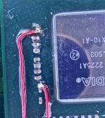
yes, I noticed this problem at the assembly stage and fixed it, it's just that this is the first photo, 50 ohm resistors, other people put them, they also work like 47Your 50 (49.9) ohm resistors threw me a little bit, but those should be alright, considering you were booting. Is it possible that your wire attached to the resistor on pin 26 is intermittently hitting the ground pad of your removed button, and foiling the picofly glitch?
I've just received the resistors in the mail and promptly replaced the old resistors with them.must check it
51R (both 0603/0805 package) measure at about 50.2-50.4Ohms (sample size: 20 resistors) and the glitch times are expectedly just as good as with 100R in parallel and better than with the 47R resistors with the aforementioned SKHynix 64GB emmc.
I'd love to hear from rehius what his thoughts are on that matter though, before something goes electrically haywire in the long run, as I'd rather not fry my switch by assuming things.
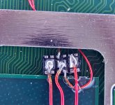
Also: Pics of the installation because everyone and their dog seems to do it.

Fluffy bits were from q-tips, before I cleaned up the flux, everything relevant was afterwards gently tacked down using 3D printing resin (The solder mask I got in China a few years ago wasn't really reacting to UV light anymore. Ew.).
Attachments
As far as I know purple screen mostly bad CMD point or blown CMD resistor.Yes it can br cold solder , purple screen it problem with EMMC

When the purple screen happened, did you use emummc or sysmmc?Greetings! Another problem. Yesterday my switch was working fine. Today I turn on - a purple screen. After the reboot, it was possible to start the drain, but after a couple of seconds an error occurred. Through time it is possible to get into the recovery menu, even did a reset to the factory settings. But still purple screen or error.
View attachment 370857
View attachment 370858
After another reboot i have this:
View attachment 370868
But then:
View attachment 370869
Yes it can br cold solder , purple screen it problem with EMMC
As far as I know purple screen mostly bad CMD point or blown CMD resistor.
It seems that the problem was really in the resistor, but I don’t know which one, so I replaced everything and it helped. At least for a while)When the purple screen happened, did you use emummc or sysmmc?

Is it charging?I've fully resolder, make data wires shorter, but still got blue->pink(or purple?). After soldering GRB/RGB points together pico shows blue->green lights (and starts ofw with 2101-0001 error). Also, can someone say do my switch have toshiba emmc or not?
Going through the thread it seems that in most cases the error you are seeing is caused by faulty M92T36 chip.
Yes, percentage goes upIs it charging?
Going through the thread it seems that in most cases the error you are seeing is caused by faulty M92T36 chip.
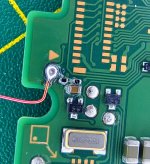
upd: forgot to mention - error disappeared after I solder ground to another point
Attachments
So @Haseo13 was right, using different soldering points fixed the issue?Yes, percentage goes up
upd: forgot to mention - error disappeared after I solder ground to another point
At first I tried to solder on the one side of emmc and also resolder ground, but it didn't help with pico, same led colors. Will try different points later and post results. Also, is it fine if I solder on board only D0, CMD and CLK, leaving power and RST on emmc?So @Haseo13 was right, using different soldering points fixed the issue?
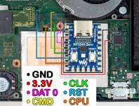
Yes, you can mix-and-match the soldering points as you see fit for your installation.At first I tried to solder on the one side of emmc and also resolder ground, but it didn't help with pico, same led colors. Will try different points later and post results. Also, is it fine if I solder on board only D0, CMD and CLK, leaving power and RST on emmc?
It seems that the problem was really in the resistor, but I don’t know which one, so I replaced everything and it helped. At least for a while)
Its not clear for me. So You replace the CMD resistor and now its working?
Anyway i'm almost sure purple screen is mostly caused by blown cmd resistor.
I replaced all threeIts not clear for me. So You replace the CMD resistor and now its working?
Anyway i'm almost sure purple screen is mostly caused by blown cmd resistor.
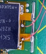
Also, when soldering to board, is it necessary to solder to one point, or i can solder to two nearby points(marked them on picture with red line on d0, cmd, clk lines)?At first I tried to solder on the one side of emmc and also resolder ground, but it didn't help with pico, same led colors. Will try different points later and post results. Also, is it fine if I solder on board only D0, CMD and CLK, leaving power and RST on emmc?
Attachments
Similar threads
- Replies
- 5
- Views
- 3K
- Replies
- 2
- Views
- 930
- Replies
- 42
- Views
- 7K
Site & Scene News
New Hot Discussed
-
-
22K views
Modders hint at potential kernel exploit hack for Xbox One consoles
It's been a while since Microsoft released the Xbox One, and despite its age, there haven't been any reliable softmod methods to hack the console. Until now. A post... -
22K views
Majora’s Mask PC port 2Ship2Harkinian gets its first release
After several months of work, the Harbour Masters 64 team have released their first public build of 2Ship2Harkinian, a feature-rich Majora's Mask PC port. This comes... -
19K views
Mario Builder 64 is the N64's answer to Super Mario Maker
With the vast success of Super Mario Maker and its Switch sequel Super Mario Maker 2, Nintendo fans have long been calling for "Maker" titles for other iconic genres... -
18K views
The founder of Oculus is releasing a $199 FPGA Game Boy system
Palmer Luckey is known for his pursuits into the world of virtual reality, having founded Oculus and designed the Rift VR headset. Prior to the $2 billion dollar... -
15K views
Nintendo takes down the Breath of the Wild randomizer mod from Gamebanana
Another day, another Nintendo DMCA takedown against fan-made content. Just a few minutes ago, Nintendo issued a DMCA takedown notice against a widely known and...by ShadowOne333 106 -
15K views
The Kingdom Hearts games are coming to Steam
After a little more than three years of exclusivity with the Epic Games Store, Square Enix has decided to bring their beloved Kingdom Hearts franchise to Steam. The... -
14K views
Doom for SNES full source code released by former Sculptured Software employees
The complete source code for the Super Nintendo Entertainment System (SNES) version of Doom has been released on archive.org. Although some of the code was partially... -
12K views
Select PlayStation 2 games are coming to PlayStation 5
Sony is once more attempting to reintroduce players to their older library of games by re-releasing classic PlayStation 2 titles onto the PlayStation Store. During... -
12K views
Skyward Sword HD randomizer announced with release date and trailer
Skyward Sword is a divisive title in the Zelda series. Hailed with praise at launch with a 93 Metacritic average, the game since received criticism for the... -
10K views
PlayStation State of Play May 2024 showcase - God of War: Ragnarok coming to PC
The latest State of Play is here. This is PlayStation's Summer showcase, providing updates to new updates on upcoming games and brand new reveals. The 35-minute...
-
-
-
169 replies
The founder of Oculus is releasing a $199 FPGA Game Boy system
Palmer Luckey is known for his pursuits into the world of virtual reality, having founded Oculus and designed the Rift VR headset. Prior to the $2 billion dollar...by Chary -
131 replies
Modders hint at potential kernel exploit hack for Xbox One consoles
It's been a while since Microsoft released the Xbox One, and despite its age, there haven't been any reliable softmod methods to hack the console. Until now. A post...by Chary -
108 replies
Majora’s Mask PC port 2Ship2Harkinian gets its first release
After several months of work, the Harbour Masters 64 team have released their first public build of 2Ship2Harkinian, a feature-rich Majora's Mask PC port. This comes...by Scarlet -
106 replies
Nintendo takes down the Breath of the Wild randomizer mod from Gamebanana
Another day, another Nintendo DMCA takedown against fan-made content. Just a few minutes ago, Nintendo issued a DMCA takedown notice against a widely known and...by ShadowOne333 -
91 replies
The Kingdom Hearts games are coming to Steam
After a little more than three years of exclusivity with the Epic Games Store, Square Enix has decided to bring their beloved Kingdom Hearts franchise to Steam. The...by Chary -
79 replies
Select PlayStation 2 games are coming to PlayStation 5
Sony is once more attempting to reintroduce players to their older library of games by re-releasing classic PlayStation 2 titles onto the PlayStation Store. During...by Chary -
69 replies
Nintendo Direct announced for tomorrow, June 18th, 2024
Nintendo have officially announced a Nintendo Direct for tomorrow, June 18th. The show will focus on Switch titles releasing this year and they have explicitly...by shaunj66 -
66 replies
Mario Builder 64 is the N64's answer to Super Mario Maker
With the vast success of Super Mario Maker and its Switch sequel Super Mario Maker 2, Nintendo fans have long been calling for "Maker" titles for other iconic genres...by Scarlet -
64 replies
PlayStation State of Play May 2024 showcase - God of War: Ragnarok coming to PC
The latest State of Play is here. This is PlayStation's Summer showcase, providing updates to new updates on upcoming games and brand new reveals. The 35-minute...by Chary -
64 replies
Doom for SNES full source code released by former Sculptured Software employees
The complete source code for the Super Nintendo Entertainment System (SNES) version of Doom has been released on archive.org. Although some of the code was partially...by shaunj66
-
Popular threads in this forum
General chit-chat
-
 Sicklyboy
Loading…
Sicklyboy
Loading…
-
 @
BakerMan:
plus there's thunder and lightning outside, and it'll rain soon, there's somehow no tornado watch tho
@
BakerMan:
plus there's thunder and lightning outside, and it'll rain soon, there's somehow no tornado watch tho -
@
BakerMan:
and to make it worse, the heat didn't sway my brother away from wanting to spend some time swimming on his birthday tomorrow
-
-
-
-
-
-
@
BakerMan:
if you have a habitable basement, the heat shouldn't be down there and that's where you should hang out
-
-
-
-
-
-
-
-
-
-
@
BakerMan:
fuck this heatwave, i don't usually sleep with a fan, but i believe the fan is getting put on the bed rather than beside it
-
-
-
 @
BigOnYa:
Yea it was 96 F for the high, 78 F for the low today, in Ohio, bout same for bakerman in Michigan
@
BigOnYa:
Yea it was 96 F for the high, 78 F for the low today, in Ohio, bout same for bakerman in Michigan -
-
-
-